
Foldable frame assembly for suspending a machine above a ground surface

a technology of folding frame and machine, which is applied in the direction of folding cycles, carriages/perambulators with multiple axes, child seats, etc., can solve the problems of user danger, difficulty in folding the first and second propping frames, and the conventional frame assembly b>10/b> is only suitable, so as to achieve convenient and safe folding and unfolding

Inactive Publication Date: 2006-04-13
P & F BROTHER INDAL
View PDF8 Cites 26 Cited by
  • Summary
  • Abstract
  • Description
  • Claims
  • Application Information

AI Technical Summary

Benefits of technology

"The present invention provides a foldable frame assembly that can safely and conveniently fold and unfold to support machines of different sizes. The assembly includes a base frame, a prop member to lift the frame from a laid-down position to a standing position, a wheel unit for easy movement on a ground surface, a tabletop for supporting a machine, and a bracing member to secure the machine in place. The assembly also includes a rear locking unit to prevent movement of the tabletop when in use. The technical effects of this invention include improved portability, safety, and flexibility for supporting machines in different situations."

Problems solved by technology

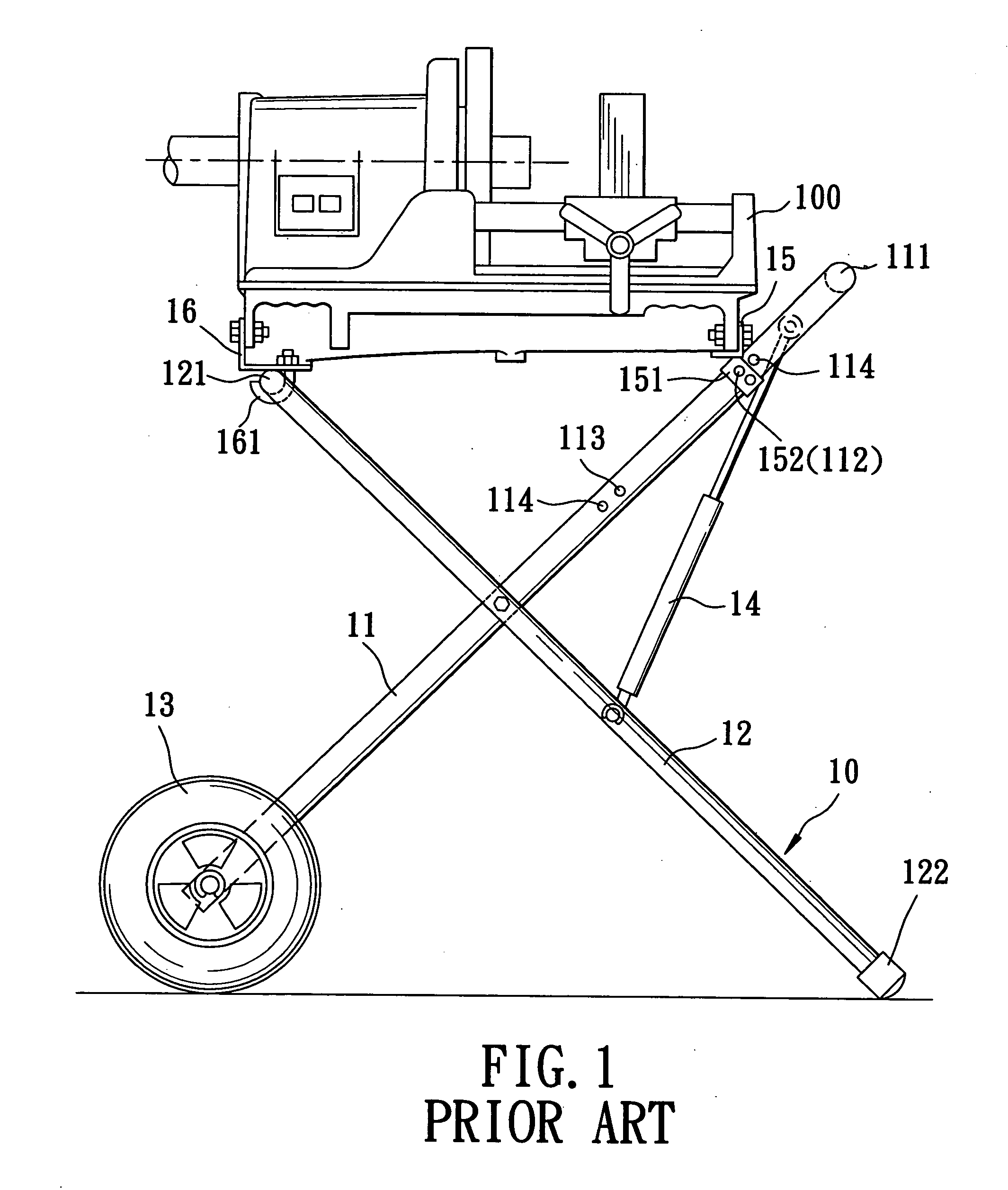
However, it is difficult for the user to fold the first and second propping frames 11, 12 because his both hands are already occupied.
Moreover, during the folding operation, the frame assembly 10 tends to move undesirably because of the wheels 13, which may result in danger to the user.
Furthermore, the conventional frame assembly 10 is only suitable for supporting and carrying machines of a fixed dimension.

Method used


Image

  • Foldable frame assembly for suspending a machine above a ground surface
  • Foldable frame assembly for suspending a machine above a ground surface
  • Foldable frame assembly for suspending a machine above a ground surface

Examples


Embodiment Construction

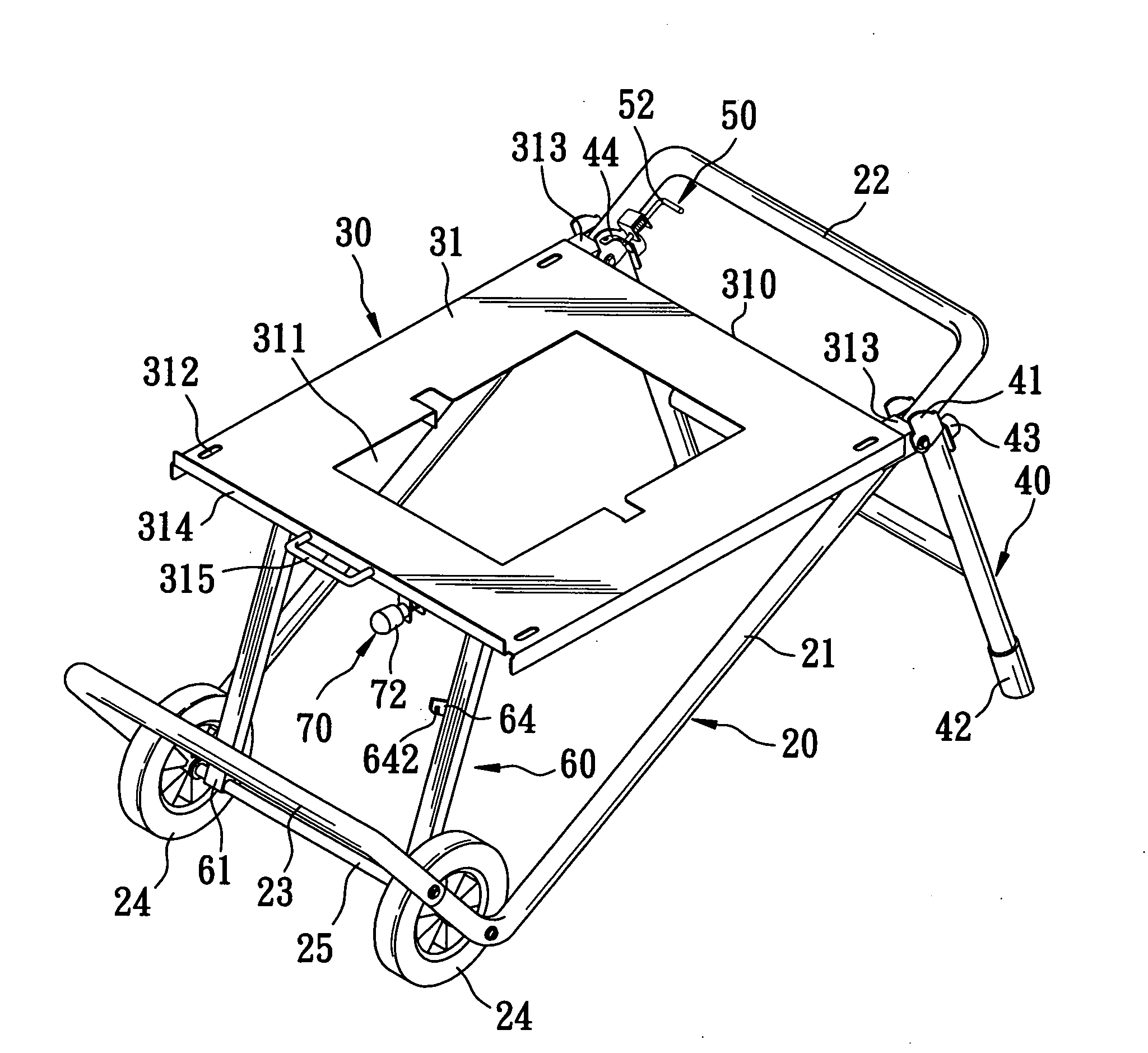
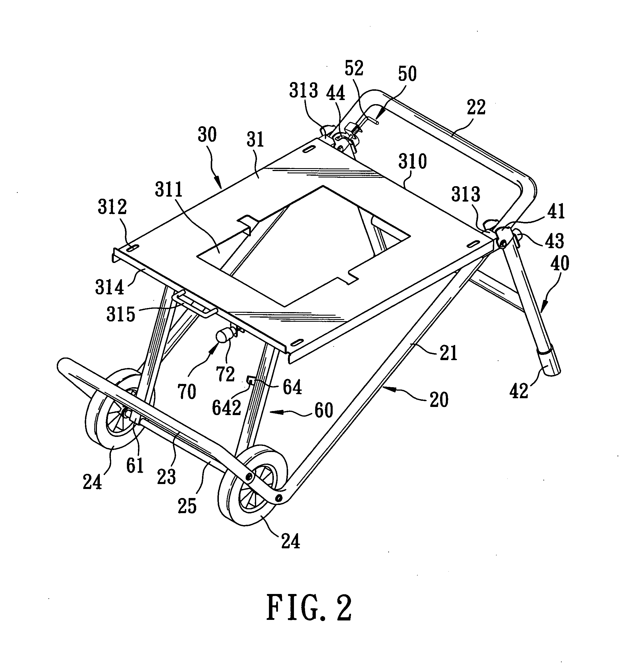
[0021] Referring to FIGS. 2 and 3, the preferred embodiment of a foldable frame assembly according to the present invention is shown to comprise abase frame 20, a prop member 40, a tabletop unit 30, a front locking unit 50, a bracing member 60, and a rear locking unit 70. The base frame 20 includes a wheel-carrying end 25 in the form of a wheel axle which extends in a transverse direction and which defines a wheel axis, and a handgrip end 22 in the form of a handgrip shaft which extends in the transverse direction and which is disposed opposite to the wheel-carrying end 25 in a longitudinal direction that is transverse to the transverse direction, and an intermediate portion 21 including two parallel lateral arms which are connected to and which are interposed between the wheel-carrying end 25 and the handgrip end 22. A wheel unit includes two wheels 24 mounted rotatably on the wheel axle and disposed proximate to the lateral arms, respectively, so as to rest on a ground surface.

[0...


PUM


Abstract

A foldable frame assembly includes a base frame having a wheel-carrying end for mounting a wheel unit, a handgrip end, and an intermediate portion connected to a prop member so as to lift the base frame to a standing position. A tabletop has a front tabletop end pivoted to the intermediate portion for suspending a machine above the ground surface so as to enable a rear tabletop end to turn from a working position to a folded position. A bracing member has an anchoring end pivotally mounted on the wheel-carrying end, and a slidable end coupled with the rear tabletop end such that when the rear tabletop end is turned from the working position to the folded position, the slidable end is turned to be close to the intermediate portion. A rear locking unit is disposed to guard against movement of the slidable end.

Description

BACKGROUND OF THE INVENTION [0001] 1. Field of the Invention [0002] This invention relates to a foldable frame assembly for suspending a machine, such as a sawing, cutting or planing machine, above a ground surface, more particularly to a foldable frame assembly which can be folded and unfolded conveniently and which can be adapted for suspending machines of different sizes. [0003] 2. Description of the Related Art [0004] Referring to FIG. 1, a conventional foldable frame assembly 10 is shown to include first and second propping frames 11, 12, a pair of wheels 13, a hydraulic cylinder unit 14, and front and rear carrying frames 15, 16. The first and second propping frames 11, 12 are pivotally connected to each other at middle portions thereof. The first propping frame 11 has an upper end formed as a handle 111, a lower end for mounting the wheels 13, and a middle portion formed with first and second positioning holes 112, 113 and two barrier pins 114 adjacent to the first and second...

Claims


Application Information

Patent Timeline
Patent Type & Authority Applications(United States)
IPC IPC(8): A47B3/00B23Q1/76
CPCB25H1/04F16M3/00
Inventor CHEN, YU-TIENCAI, QING-YAOHUNG, YA-LING
Owner P & F BROTHER INDAL
Learn More