Method for magnetron sputter deposition

a magnetron sputter and sputtering technology, applied in the field of methods, can solve the problems of inefficiency and/or ineffectiveness of the magnetron sputtering system used to form such coatings

a magnetron sputter and sputtering technology, applied in the field of methods, can solve the problems of inefficiency and/or ineffectiveness of the magnetron sputtering system used to form such coatings

US20060076231A1Inactive Publication Date: 2006-04-13SOUTHWEST RES INST

Image

  • Method for magnetron sputter deposition
  • Method for magnetron sputter deposition
  • Method for magnetron sputter deposition

Examples


Embodiment Construction

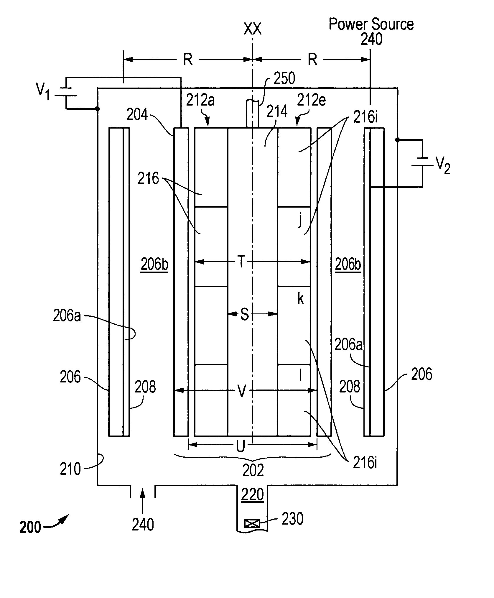
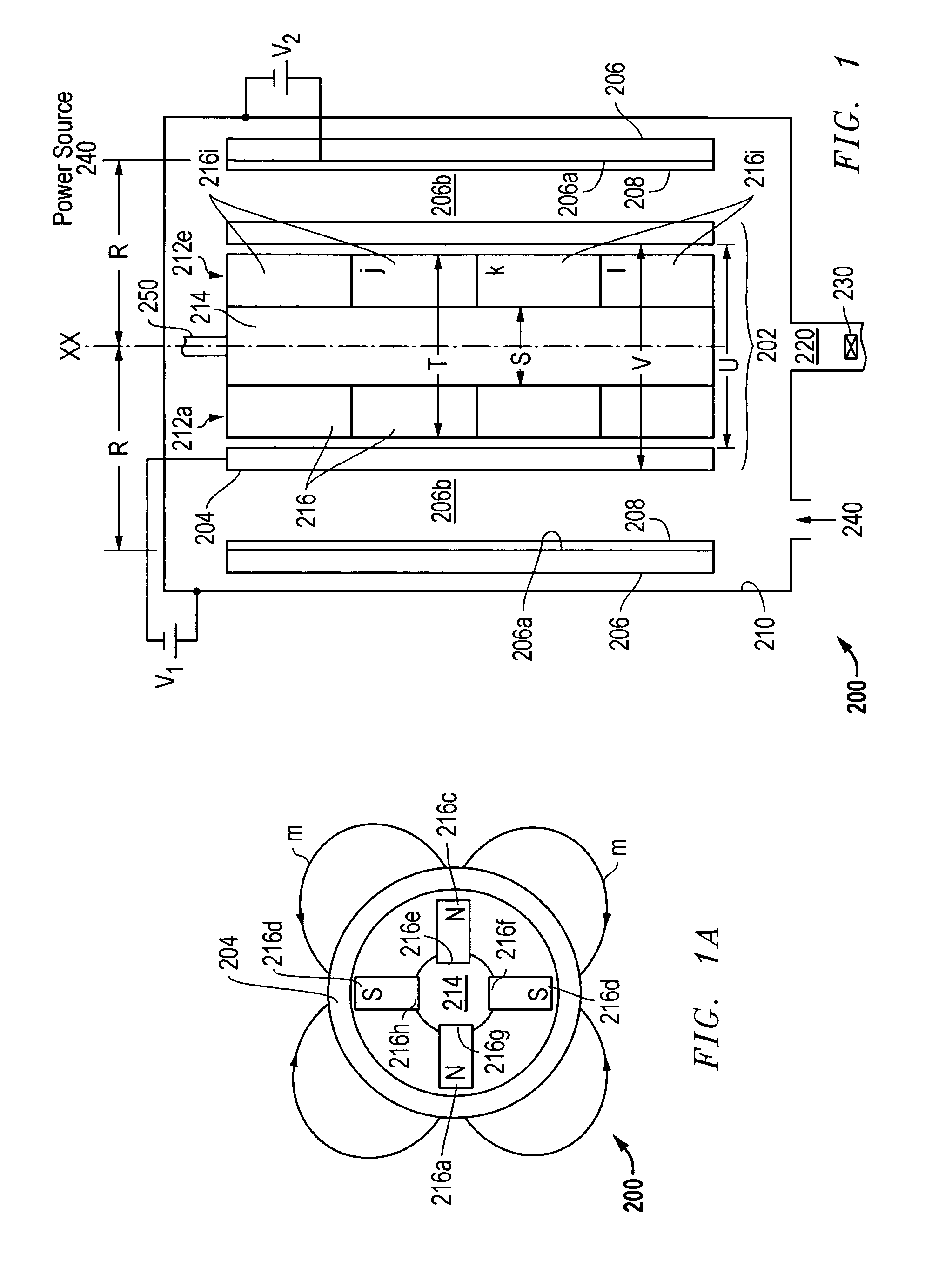
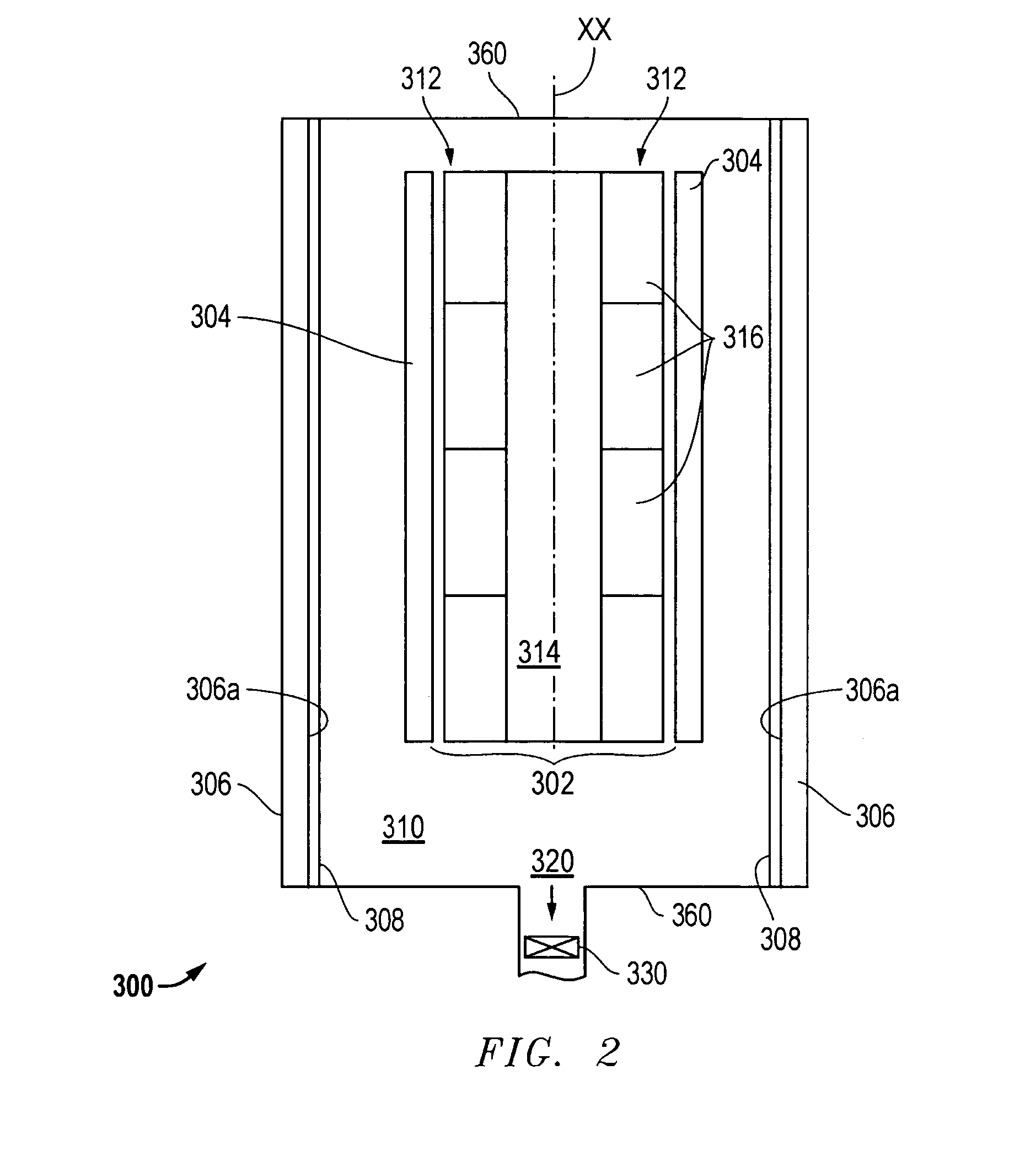
[0016] The present application provides a system, apparatus, and method of depositing a coating on an interior surface of a substrate or workpiece utilizing a magnetron sputtering process. The method of deposition is implemented through operation of a magnetron sputtering system or assembly that includes a magnetron sputtering apparatus (“magnetron”) and the workpiece. The magnetron comprises a sputter target material, from which sputter material is ejected and directed to the workpiece surface to be coated.

[0017] The workpiece is positioned in the vicinity of the magnetron and preferably, such that the interior surface to be coated is facing the sputter target material. The system, apparatus, and method herein are particularly suited for depositing a coating on a hollowed workpiece. Suitable workpieces comprise a hollow or space defined by an interior wall in which the magnetron is positioned. More preferably, the hollowed workpiece comprises a tubular structure having an elongate...


PUM

PropertyMeasurementUnit
Temperatureaaaaaaaaaa

Abstract

A method for depositing a coating on an interior surface of a hollowed workpiece. The method comprises providing the hollowed workpiece in a vacuum chamber, the hollowed workpiece comprising an interior surface substantially defining a bore having a longitudinal axis; positioning a magnetron within thed bore along substantially the length of said longitudinal axis and substantially radially equidistant from the interior surface, said magnetron comprising an external sputter target material; and, generating a circumferential magnetic field about the sputter target material for a time and under sputter deposition conditions effective to produce an interior surface comprising a substantially uniform coating comprising said sputter target material.

Description

CROSS-REFERENCE TO RELATED APPLICATIONS [0001] The present application is related to the application entitled “System and Apparatus for Magenetron Sputter Deposition, ” filed simultaneously herewith.FIELD OF THE APPLICATION [0002] The present application relates generally to a method of depositing a coating on a workpiece. BACKGROUND [0003] Tubular workpieces, such as gun barrels and engine cylinders, often require hard, wear-resistant, and / or corrosion resistant interior coatings. A number of techniques have been used to coat interior tubular surfaces, including magnetron sputtering. Unfortunately, the magnetron sputtering systems used to form such coatings generally have been inefficient and / or ineffective. More efficient and effective methods for applying such coatings are needed. BRIEF SUMMARY [0004] The present application provides a method for depositing a coating on an interior surface of a hollowed workpiece. The method comprises providing the hollowed workpiece in a vacuum ...

Claims


Application Information

Patent Timeline
13 Apr 2006
Publication
US20060076231A1
IPC
C23C14/00; C23C14/32
CPC
C23C14/046; C23C14/35; H01J37/3405
Inventors
WEI, RONGHUA