
Engine torque control device

Active Publication Date: 2006-04-13
NISSAN MOTOR CO LTD
View PDF5 Cites 13 Cited by
  • Summary
  • Abstract
  • Description
  • Claims
  • Application Information

AI Technical Summary

Benefits of technology

[0008] The present invention was conceived in light of these problems encountered in the past. One object of the present invention is to provide an engine torque control device that reduces shift shock while improving shift response by shortening the shift time.

Problems solved by technology

It has been discovered that with the conventional device described above, since the throttle opening is fixed while the clutch is disengaged during a shift, control that is suited to all engine operating conditions cannot be performed, and there is the danger that engine speed will rise too high.
Furthermore, since there is response lag in the engine speed with respect to the throttle opening command value, elevated engine speed cannot be quickly lowered, and as a result, the time it takes to reach the synchronizing speed, that is, the shift time, is longer, which adversely affects shift response.

Method used


Image

  • Engine torque control device
  • Engine torque control device
  • Engine torque control device

Examples


Embodiment Construction

[0017] Selected embodiments of the present invention will now be explained with reference to the drawings. It will be apparent to those skilled in the art from this disclosure that the following descriptions of the embodiments of the present invention are provided for illustration only and not for the purpose of limiting the invention as defined by the appended claims and their equivalents.

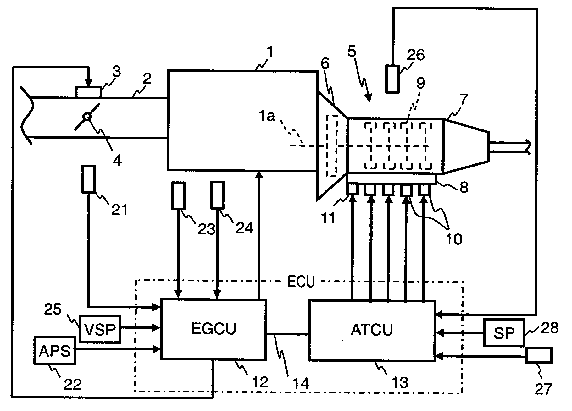
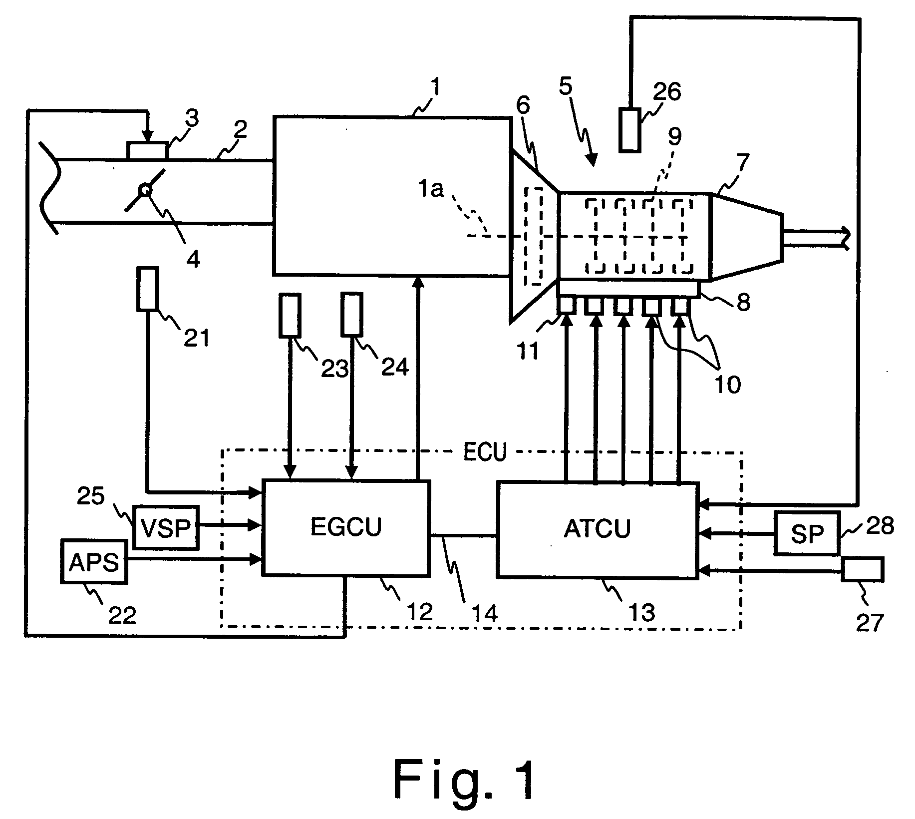
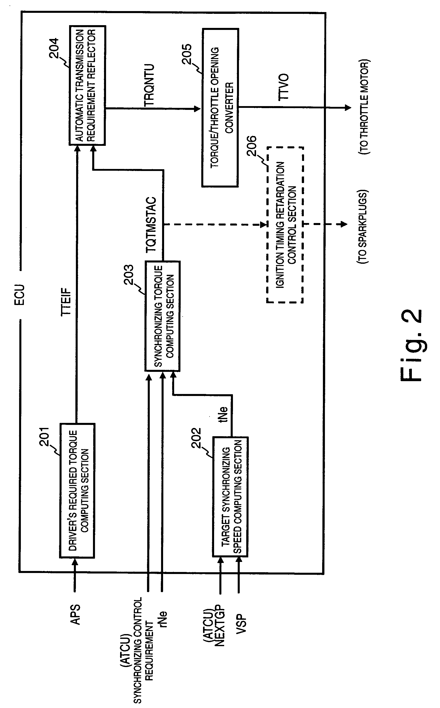
[0018] Referring initially to FIG. 1, an internal combustion engine 1 is schematically illustrated that is equipped with an engine torque control device or system in accordance with one embodiment of the present invention. In FIG. 1, the engine 1 receives intake air through an air intake passage 2 such that the intake air is supplied to each cylinder of the engine 1. The intake air passing through the air intake passage 2 to each cylinder is regulated by controlling a throttle motor 3 that operates a throttle valve 4. The operation of the throttle valve 4 by the throttle motor 3 can be accomplish...


PUM


Abstract

An engine torque control device is configured to reduce shift shock while shortening shift time and improving shift response in an engine equipped with a shifting unit. In the engine torque control device engine output torque is subjected to feedback control so that the engine speed will be the target speed (synchronizing speed) after a downshift. The feedback control includes at least a proportional control and a differential control. The differential control is halted until the difference between the synchronizing speed and the actual engine speed is equal to or less than a specified value. Differential control is only performed at or below this specified value.

Description

CROSS-REFERENCE TO RELATED APPLICATIONS [0001] This application claims priority under 35 U.S.C. § 119 to Japanese Patent Application No. 2004-297783. The entire disclosure of Japanese Patent Application No. 2004-297783 is hereby incorporated herein by reference. BACKGROUND OF THE INVENTION [0002] 1. Field of the Invention [0003] The present invention relates to an engine torque control device to which a shifting unit is linked, and more particularly relates to an engine torque control device that reduces shift shock during downshifting. [0004] 2. Background Information [0005] An example of an engine torque control device that reduces shift shock is the one disclosed in Japanese Laid-Open Patent Publication No. 2001-328461. With this device, the throttle is fixed at a specific opening while the clutch is disengaged during a shift so that the synchronizing speed, which is used for synchronizing the engine speed to the clutch output speed, can be quickly attained. After which, the thro...

Claims


Application Information

Patent Timeline
IPC IPC(8): G06F17/00B60W10/00B60W10/02B60W10/04B60W10/06B60W10/10B60W10/11F02D9/02F02D11/10F02D29/00F02D41/14F02D43/00F02D45/00F02P5/15F16H59/42F16H61/04F16H61/68F16H63/40F16H63/50
CPCB60W10/06B60W10/11B60W30/19B60W2540/10F02D31/001F02D41/023F02D41/1488F02D2041/1409F16H61/0403F16H63/502F16H2059/363F16H2061/0216B60W2050/0009B60W20/00
Inventor SHIMADA, TETSUYAIRIYAMA, MASAHIRO
Owner NISSAN MOTOR CO LTD
Learn More