Navigation and viewing in a multidimensional space

a multi-dimensional space and navigation technology, applied in the direction of mechanical pattern conversion, static indicating devices, instruments, etc., can solve the problems of inability to intuitively use, inherently two-dimensional navigation, and still problematic in higher dimensions

Inactive Publication Date: 2006-04-13
ANDERSON THOMAS G
View PDF4 Cites 64 Cited by
  • Summary
  • Abstract
  • Description
  • Claims
  • Application Information

AI Technical Summary

Benefits of technology

[0011] The present invention provides a multidimensional display controller adapted for use with multidimensional information, especially for use in virtual reality or other computer displays. The display controller allows a user to establish a base viewing location and a base viewing orientation. The user can also establish a relative viewing orientation. The display controller combines the base viewing orientation and relative viewing orientation to determine a desired viewing orientation. The display controller depicts an aspect of the multidimensional space visible along the desired viewing orientation. The user can establish the base viewing location and base viewing orientation by moving a user-defined point (or multiple points, which define an object) relative to the multidimensional space or relative to a separate reference frame, or by some other type of input such as by changing an input object. The user can change the relative viewing orientation by changing the location, orientation, deformation, or other property of an input object. The relative viewing orientation can also be changed by tracked user body motions, for example by tracked motion of the user's head or eyes.

Problems solved by technology

While the ubiquitous mouse has all but conquered navigation in two-dimensional spaces, navigation in higher dimensions is still problematic.
They are inherently two-dimensional devices, however, and are not intuitive to use when adapted for use in more dimensions.
The spaceball does not provide intuitive control of motion because the spaceball itself cannot move.
A spaceball can control relative motion, but is ill-suited for large displacement or absolute motion.
Booms and head mounted displays can be expensive, however, and the physical limits of the boom structure can limit intuitive navigation.
Booms can control relative motion, but are ill-suited for large displacement or absolute motion.
These are often expensive and too bulky for desktop use.
They are also intrusive, often requiring the user to be strapped in to the device.
Changing directions in the dimensions using a treadmill or bicycle can also be non-intuitive.
These can be intuitive since they can move in multiple dimensions, but they do not allow nonvisual feedback to the user.
Tracking can also be difficult when, for example, an electromagnetically tracked device is used near large metal items or an acoustically tracked device is used in settings where line of sight is difficult to maintain.

Method used


Image

  • Navigation and viewing in a multidimensional space
  • Navigation and viewing in a multidimensional space
  • Navigation and viewing in a multidimensional space

Examples


Embodiment Construction

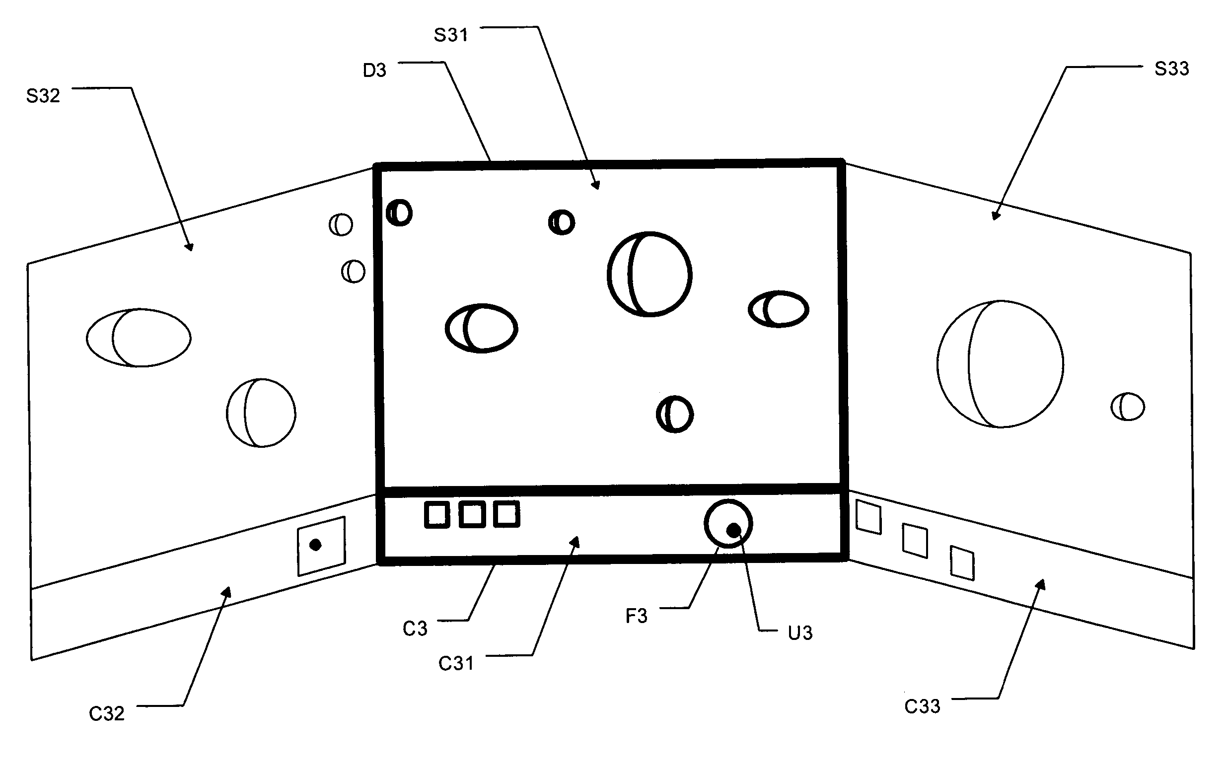
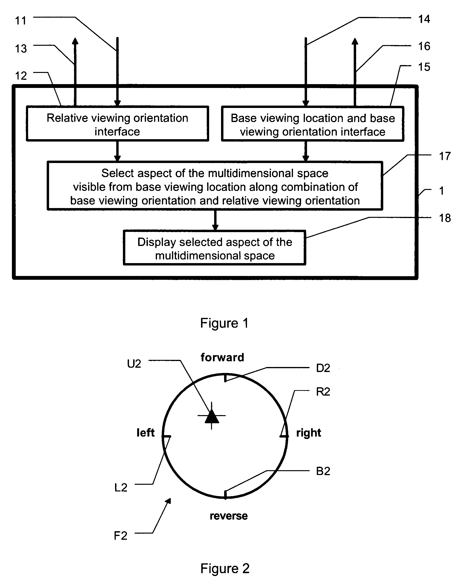
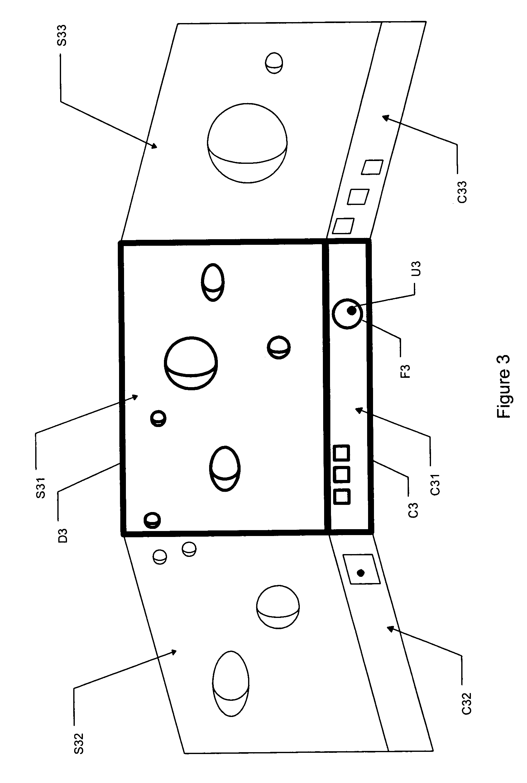
[0025] The present invention provides a display controller adapted for use with multidimensional information, especially for use in virtual reality or other computer displays. FIG. 1 illustrates the information flow in an example display controller 1 according to the present invention. A user can provide input 14 to indicate a base viewing location and base viewing orientation. Base viewing location and base viewing orientation interface 15 transforms the user input 14 to establish a base viewing location and base viewing orientation, and can provide feedback 16 associated with the base viewing location and base viewing orientation to the user. The user can also provide input 11 to indicate a relative viewing orientation. Relative viewing orientation interface 12 transforms the user input 11 to establish a relative viewing orientation, and can provide feedback 13 associated with the relative viewing orientation to the user. The display controller 1 combines the base viewing orientat...


PUM


Abstract

A display controller allows a user to control a base viewing location, a base viewing orientation, and a relative viewing orientation. The base viewing orientation and relative viewing orientation are combined to determine a desired viewing orientation. An aspect of a multidimensional space visible from the base viewing location along the desired viewing orientation is displayed to the user. The user can change the base viewing location, base viewing orientation, and relative viewing orientation by changing the location or other properties of input objects.

Description

CROSS REFERENCE TO RELATED APPLICATIONS [0001] This application claims priority as a continuation of U.S. patent application Ser. No. 11 / 244,584 (“Anderson IV”), titled “Navigation and Viewing in a Multidimensional Space,” filed Oct. 6, 2005, incorporated herein by reference; which application claimed priority as a continuation-in-part of U.S. patent application Ser. No. 09 / 785,696 (“Anderson III”), filed on Feb. 16, 2001, incorporated herein by reference; which claimed the benefit of U.S. Provisional Application 60 / 202,448 (“Anderson II”), filed on May 6, 2000, incorporated herein by reference; and was a continuation-in-part of U.S. patent applications Ser. No. 08 / 834,642 (“Anderson I”) and 08 / 834,616 (“Davidson”), now U.S. Pat. No. 6,208,349, each of which was filed on Apr. 14, 1997, each of which is incorporated herein by reference.GOVERNMENT RIGHTS [0002] This invention was made with Government support under Contract DE-AC04-94AL85000 awarded by the U.S. Department of Energy. Th...

Claims


Application Information

Patent Timeline
Patent Type & Authority Applications(United States)
IPC IPC(8): G06F3/00G09G5/08G06T15/20
CPCG06F3/016G06F3/04815G06T15/20G06T19/003
Inventor ANDERSON, THOMAS G.
Owner ANDERSON THOMAS G
Why Eureka
Try Eureka