
Self-propelled cleaner charging-type travel system and charging-type travel system

a technology of self-propelled cleaning and charging type, which is applied in the direction of vehicle position/course/altitude control, process and machine control, instruments, etc., can solve the problems of high cost of charging type, easy error, and precise travel of self-propelled devices, so as to facilitate restraining, raise cost, and positively subject

Inactive Publication Date: 2006-04-20
FUNAI ELECTRIC CO LTD
View PDF19 Cites 48 Cited by
  • Summary
  • Abstract
  • Description
  • Claims
  • Application Information

AI Technical Summary

Benefits of technology

[0006] The present invention has been made in view of the foregoing problems. It is an object of the present invention to provide a charging-type travel system that facilitates restraining of raising cost, and can cause a self-propelled device to be precisely self-traveled to a charger device and then cause the travel device to be positively subjected to charging.
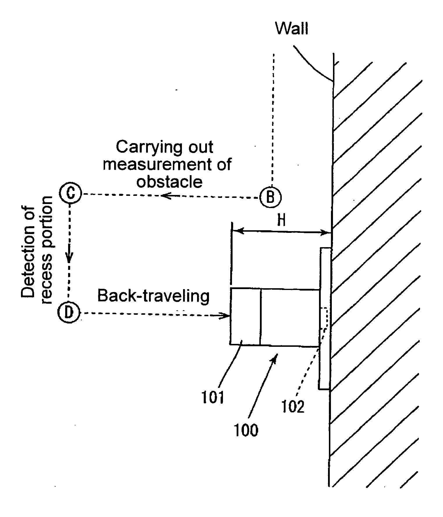
[0010] The automatic charge-controlling unit is adapted to cause the travel device to be traveled along the wall of the room. The automatic charge-controlling unit includes the charger device-search controlling means that is adapted to cause the travel device to turn through an angle of 90° when data representing that a forward obstacle is detected by the forward obstacle sensors are given during the traveling of the travel device along the wall of the room, measure a depth of the same obstacle while causing the travel device to be moved perpendicularly to the wall, and then judge on the basis of the measuring results whether or not the obstacle is the charger device. Namely, in the charging-type travel system according to claim 2, the travel device conducts a search for the charger device set on the wall while traveling along the same wall. Therefore, there is no need to provide a guidance device for guiding the travel device to the charger device, on the side of the charger device, and it is therefore possible to restrain an increase in the cost of the self-propelled system. Furthermore, the travel device conducts the search for the charger device, so that it can be precisely traveled to the location where the charger device is set.
[0015] In this aspect of the present invention that is constructed as discussed above, for example, in a case where the above-mentioned recess portion through the sensors is provided just below the electrical supply terminal provided at the charger device, when the travel device that has detected the recess portion is to be stopped, the travel device is stopped at a position where the travel device is opposed to the electrical supply terminal. Thus, it is possible to easily conduct the position-registering between the above-mentioned travel device and the above-mentioned charger device.
[0017] In this aspect of the present invention that is constructed as described above, it is possible to conduct the electrical connection between the charging terminal and the electrical supply terminal by merely causing the travel device body to be moved back after the 90° turn is performed.
[0019] According to this aspect of the present invention that is constructed as described above, there is no need for a user to perform cleaning of a room while carrying a cleaner. Therefore, this aspect can reduce the user's burden.
[0021] In this aspect of the present invention that is constructed as described above, it is possible to restrain the power used (for example, power to be used during the traveling along the wall) during the automatic charging-process is conducted.

Problems solved by technology

Of the above-mentioned prior art systems, in the charging-type self-travel system disclosed in Japanese Patent Application Laid-Open Nos. Hei. 7-8428 and Hei. 4-53515, a guidance mechanism for guiding the self-propelled device to the charger device is provided on the side of the charger device, so that there is a problem that the cost of the charger device is increased.
However, when the present position of the self-propelled device is judged from the moving amount of the self-propelled device, an error is apt to occur, so that there is a problem that it is difficult to cause the self-propelled device to be precisely traveled to the charger device.

Method used


Image

  • Self-propelled cleaner charging-type travel system and charging-type travel system
  • Self-propelled cleaner charging-type travel system and charging-type travel system
  • Self-propelled cleaner charging-type travel system and charging-type travel system

Examples


Embodiment Construction

[0037] Now, embodiments of the present invention will be discussed hereinafter in the following order:

[0038] (1) an appearance of a self-propelled cleaner;

[0039] (2) an internal construction of the self-propelled cleaner;

[0040] (3) an operation of the self-propelled cleaner;

[0041] (4) various variants; and

[0042] (5) summary.

[0043] (1) The Appearance of the Self-Propelled Cleaner:

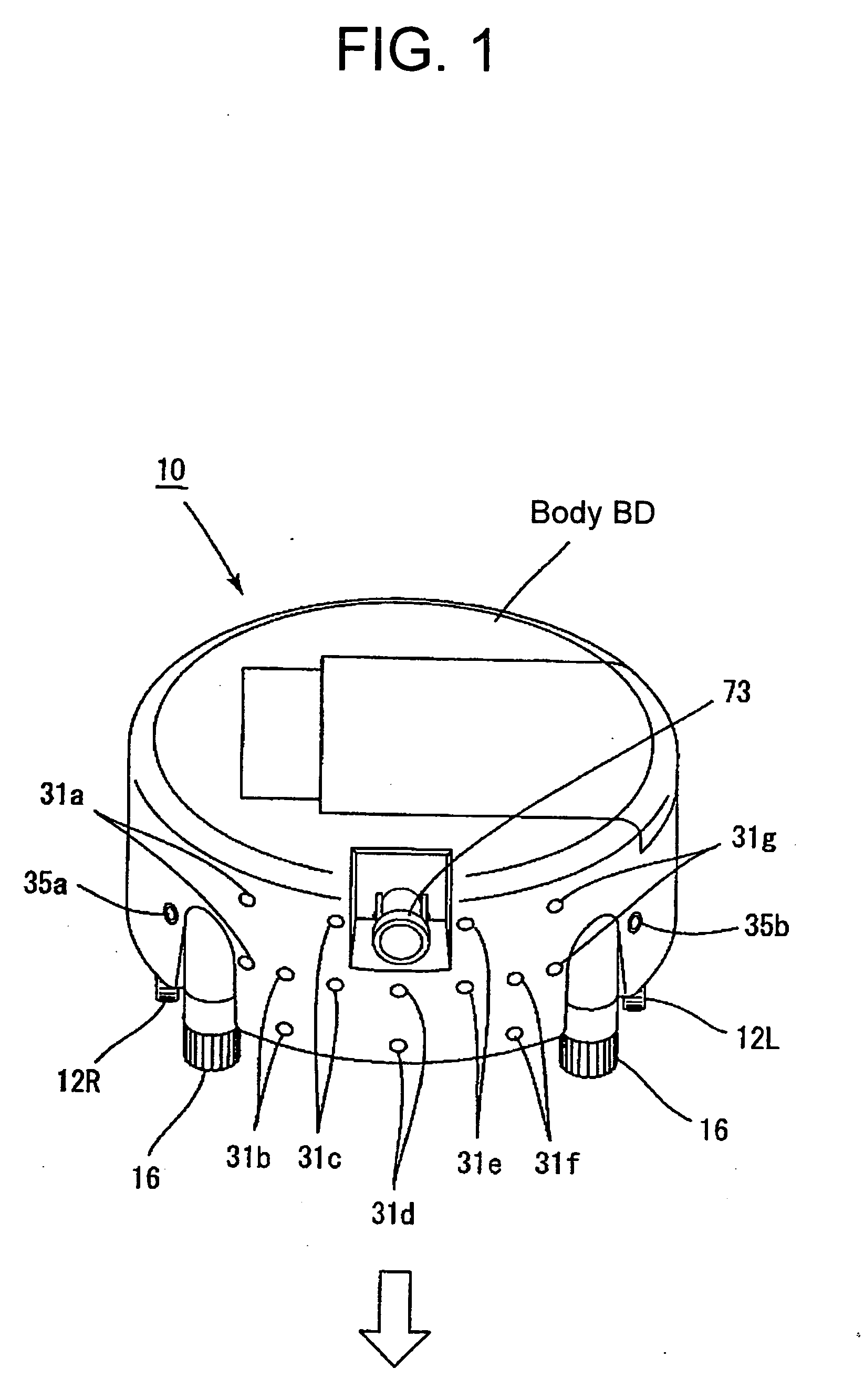
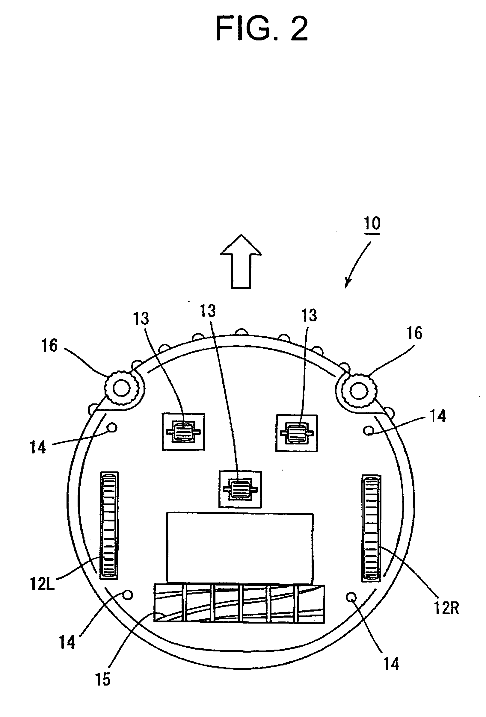
[0044]FIG. 1 is a view showing the appearance of the self-propelled cleaner according to the present invention. FIG. 2 is a bottom view of the self-propelled cleaner shown in FIG. 1. Incidentally, a direction indicated in FIG. 1 by an arrow is a traveling direction of the self-propelled cleaner at the time of advancing. As shown in FIG. 1, the self-propelled cleaner 10 according to the present invention includes a body BD of a substantially cylindrical shape and two drive wheels 12R, 12L (see FIG. 2) provided at a bottom side of the self-propelled cleaner. By driving of the drive wheels 12R, 12L separ...


PUM


Abstract

When a residual quantity of a battery of a self-propelled cleaner is decreased, automatic cleaning is interrupted and driving of a cleaner mechanism is simultaneously stopped, and when a forward obstacle is detected while allowing a self-propelled cleaner to be traveled along a wall, a rotary encoder measures a traveling distance of a cleaner body BD, thereby measuring a depth of the obstacle. Then, in a case where the measured traveling distance (X) is equal to a width (H) of a charger device that projects from the wall, it is judged that the obstacle is the charger device, and traveling of the self-propelled cleaner is controlled in such a manner that its charging terminal is operatively connected to an electrical supply terminal of the charger device. Thus said charging-type travel system is precisely self-traveled to a charger device and cause itself be positively subjected to charging.

Description

BACKGROUND OF THE INVENTION [0001] 1. Field of the Invention [0002] The present invention relates to a self-propelled cleaner charging-type travel system and a charging-type travel system and, in particular, to a system that comprises a self-propelled cleaner including a body provided with a cleaner mechanism and a driving mechanism responsible for steering and driving of the self-propelled cleaner, and a charger device for charging the self-propelled cleaner. [0003] 2. Description of the Prior Art [0004] Hitherto, regarding a charging-type travel system that comprises a self-propelled device provided with a driving mechanism responsible for steering and driving of the self-propelled device, and a charger device for charging the self-propelled device, a technique in which when a residual quantity of a battery of the self-propelled device is decreased, the self-propelled device is self-traveled to the charger device and then charged is disclosed (for example, Japanese Patent Applicat...

Claims


Application Information

Patent Timeline
IPC IPC(8): A47L5/00
CPCG05D1/0225G05D1/0242G05D1/0255G05D1/027G05D1/0272G05D2201/0203A47L2201/022A47L2201/04
Inventor TANI, TAKAO
Owner FUNAI ELECTRIC CO LTD
Learn More