
Removable gripping device which does not require the user to alter his/her grip thereon

Inactive Publication Date: 2006-04-20
SEB SA
View PDF6 Cites 10 Cited by
  • Summary
  • Abstract
  • Description
  • Claims
  • Application Information

AI Technical Summary

Benefits of technology

[0007] Since the actuation means are free to move along a direction approximately parallel to the longitudinal direction of the gripping body, no back pressure is necessary and the user can release the lever while maintaining sufficient minimum grasp to support the gripping body.
[0009] With this arrangement, to manipulate actuation means, the user must move the members forming a gripper away from the actuation means by bending his thumb. Since this maneuver is less natural than pushing the actuation means and bringing them towards the members forming a gripper, this considerably reduces the risks of the lever being extended accidentally.
[0011] Locking the lever in its retracted position in this manner prevents the members forming the gripper from being opened, even if the user suddenly manipulates the gripping device, and even if, when the members forming the gripper are in the closed position, the displacement means are close to the equilibrium position from which the members forming the gripper are moved towards their open position.
[0014] According to another embodiment, the lever and the transmission means are short, so that the user always has space to hold the gripping body with his ring finger and his little finger, only the index and the middle finger being located at the lever, and so that it reduces the movement amplitude of the lever.
[0015] According to another particular arrangement, a coil spring housed in the transmission means is used as an elastic means of the toggle joint mechanism. Consequently, unlike gripping devices according to prior art comprising a leaf spring forming a connecting rod, there is no risk of damage when the edge of the gripped container is thick.
[0016] The small moving amplitude of the lever means that the lever and the transmission means may have vertical walls arranged such that even when the lever is in the extended position, the entire mechanism is concealed and protected from any dirt accumulation.

Problems solved by technology

The problem that arises is to make a removable gripping device in which the actuation means are arranged such that the user can manipulate them and move the lever from its retracted position to its extended position without needing to alter his grip, which makes it easier to use.

Method used


Image

  • Removable gripping device which does not require the user to alter his/her grip thereon
  • Removable gripping device which does not require the user to alter his/her grip thereon
  • Removable gripping device which does not require the user to alter his/her grip thereon

Examples


Embodiment Construction

)

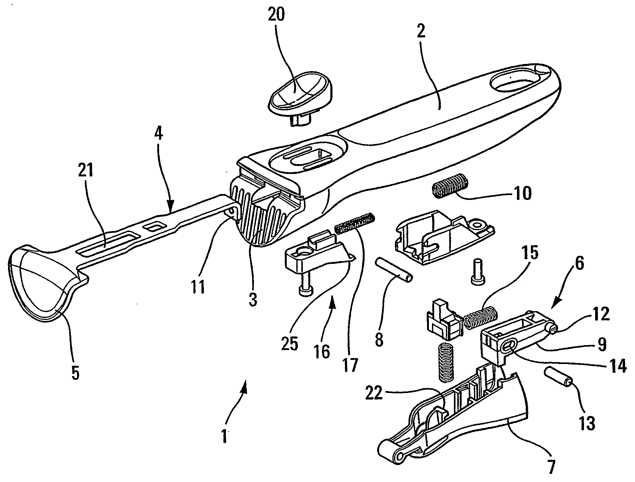
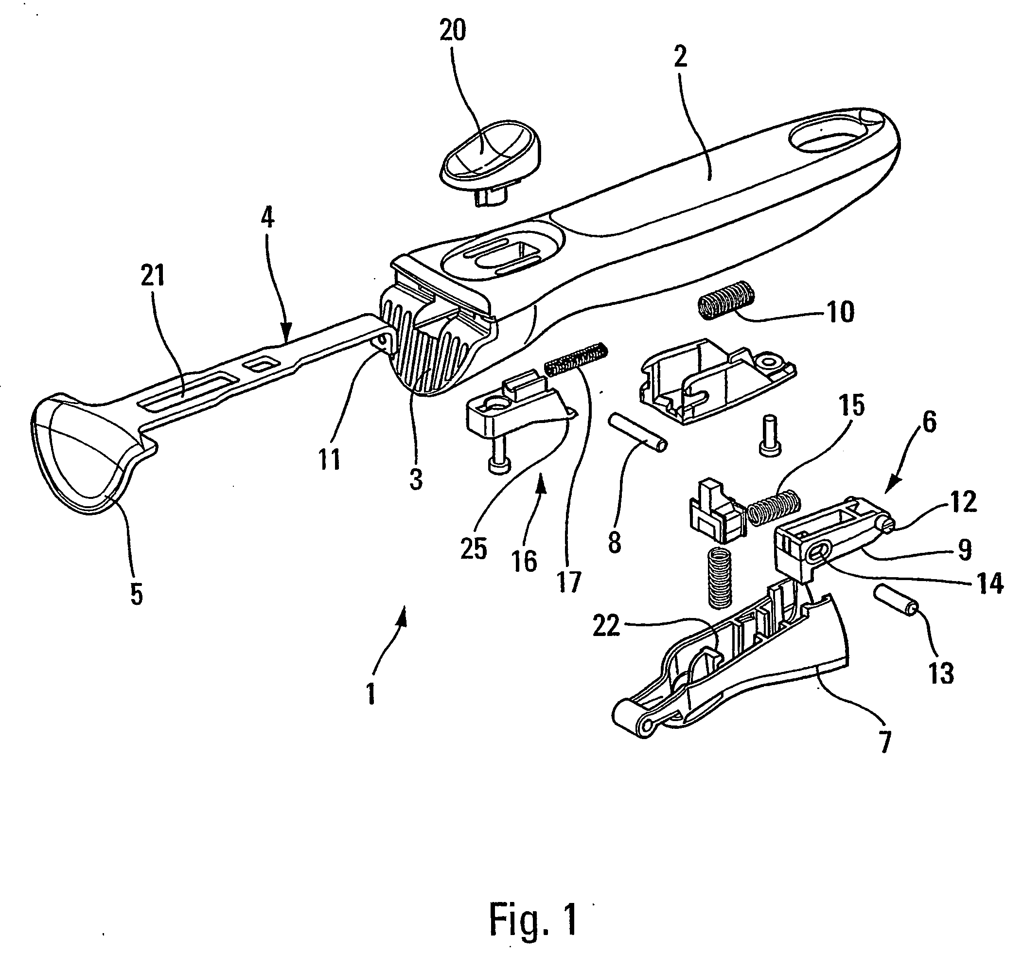
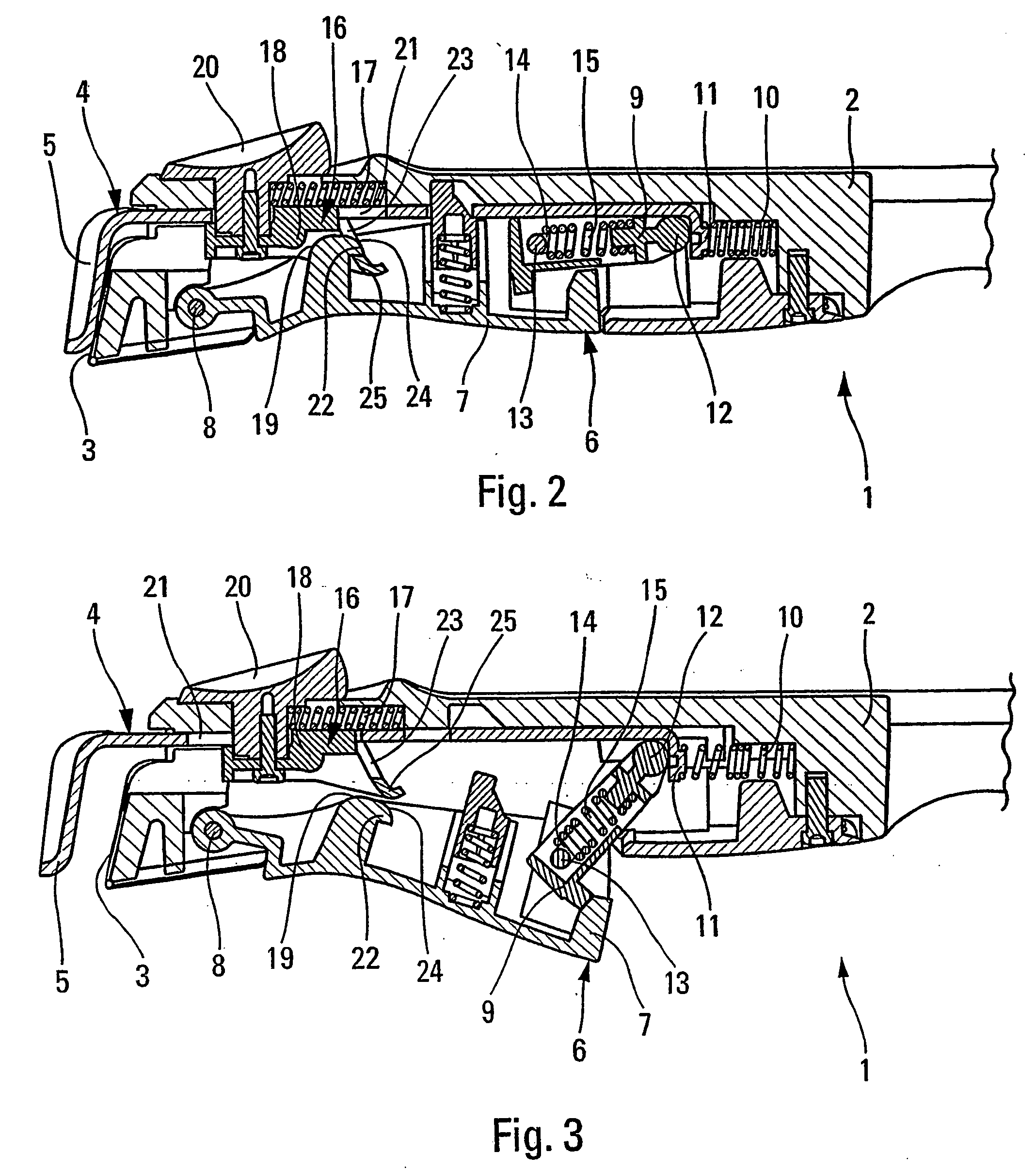
[0022] As can be seen in FIG. 1, a removable gripping device 1 for a container (for example a removable handle for a pot or pan) comprises a gripping body 2 on which two members forming a gripper 3, 4 are formed.

[0023] A first member forming a gripper 3 is fixed to one end of the gripping body 2, and the second member forming a gripper 4 is installed free to move in translation with respect to the gripping body 2, between an open position (FIG. 3) and a closed position (FIG. 2).

[0024] The mobile member forming a gripper 4 comprises a gripping end 5 which is adapted to cooperate with the fixed member forming a gripper 3, to grip an edge of the container when the mobile member forming a gripper 4 is in the closed position.

[0025] In this embodiment, the fixed member forming a gripper 3 and the gripping end 5 of the mobile member forming a gripper 4 are shaped so as to be able to grip containers for which the upper end of the edge is curved outwards and thus forms a short curved col...


PUM


Abstract

A removable gripping device for a container has two clamp-forming members which are mounted to a gripping body, one of which can move longitudinally between an open position and a closed position; movement elements which are designed to move the aforementioned mobile member; and actuation devices which can move in relation to the gripping body. The above-mentioned actuation devices are mounted so as to move longitudinally between a rest position and an actuation position, whereby the actuation devices cause a lever to move from the retracted position to the deployed position thereof.

Description

BACKGROUND OF THE INVENTION [0001] This invention relates to a removable gripping device for a container, particularly a removable handle for a pot or a pan, that can be removed without the user needing to alter his / her grip. [0002] A removable gripping device for a container of the type comprising two members forming a gripper mounted on a gripping body is known, in which one of the members forming the gripper is free to move in translation with respect to the gripping body, along a direction approximately parallel to the longitudinal direction of the gripping body between an open position and a closed position in which the members forming a gripper are adapted to grip an edge of the container, the removable gripping device comprising displacement means adapted to displacing members forming the gripper with respect to each other, said displacement means comprising a lever free to move in rotation with respect to the gripping body between an extended position and a retracted positio...

Claims


Application Information

Patent Timeline
IPC IPC(8): A23N7/00A47J45/10
CPCY10T16/4707A47J45/10
Inventor LORTHIOIR, CHRISTOPHEMONTGELARD, MICHEL
Owner SEB SA
Learn More