Payload expulsion system for deep-target penetrators

a technology of deep-target penetrators and expulsion systems, applied in the field of deep-target penetrating munitions, can solve the problems of collateral damage, payloads that cannot be deployed where intended in the interior of the facility,

Inactive Publication Date: 2006-04-20
SALIZZONI RANDY M +2
View PDF5 Cites 13 Cited by
  • Summary
  • Abstract
  • Description
  • Claims
  • Application Information

AI Technical Summary

Benefits of technology

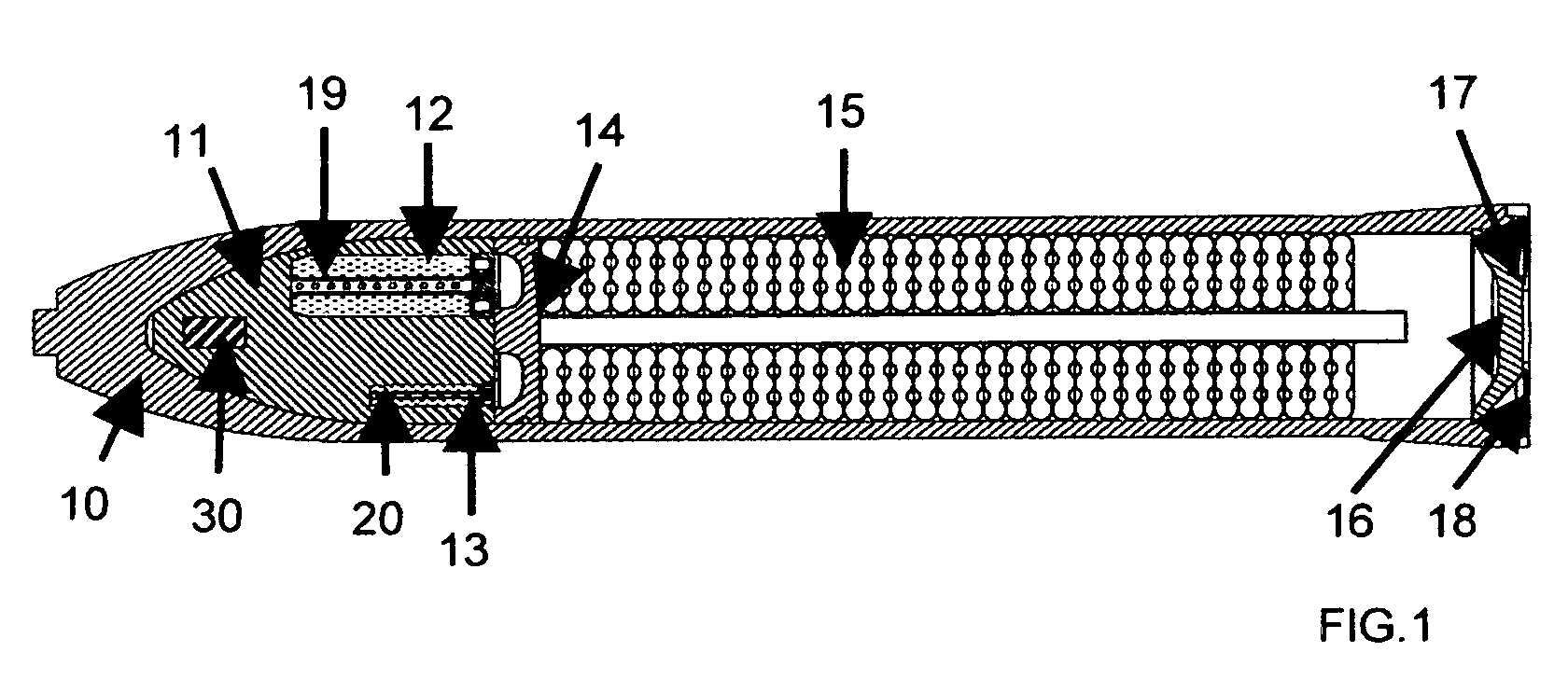
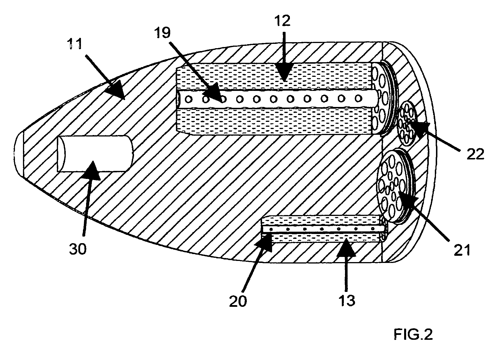
[0013] In accordance with further features of the invention, the propelling charge of the expulsion system, located in the nose cone of the penetrator, may include a number of separate fractional charges of different sizes. A shock-hardened electronic trigger system (SHETS) of the expulsion system receives the terminal velocity information from the fuze and initiates ignition of selected fractional charges to accomplish the payload expulsion in a controlled manner, including controlling the timing of the ignition of the fractional charges. The best to match the terminal velocity of the penetrator, the selected fractional charges may be ignited simultaneously or in a sequence. Because the penetrator may be damaged while penetrating the ceiling of the target facility, the timing of the expulsion events takes this into account, such that the expulsion occurs at the right time with sufficient, but not excessive, force so as to avoid rupture of the casing of the penetrator.

Problems solved by technology

Due to inertia, upon entry into the interior the penetrator retains considerable terminal velocity, such that, unless the payload is ejected in the direction opposite the direction of travel of the penetrator at a velocity to cancel the instantaneous velocity of the penetrator, the payload would fail to be deployed where intended in the facility's interior.
This could lead to collateral damage and, potentially, to dispersal of toxic materials or agents which may have been stored in the underground facility, instead of their deactivation.

Method used


Image

  • Payload expulsion system for deep-target penetrators
  • Payload expulsion system for deep-target penetrators
  • Payload expulsion system for deep-target penetrators

Examples


Embodiment Construction

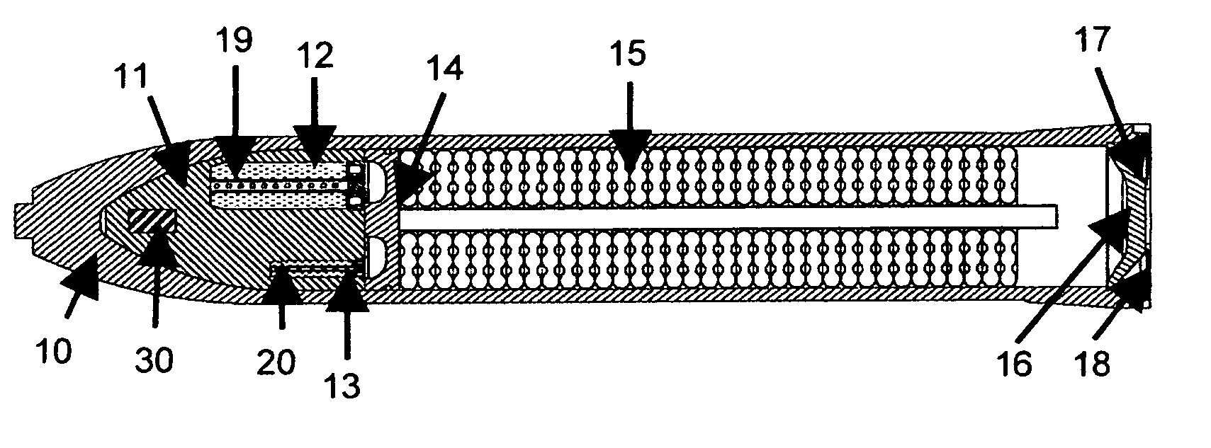
[0019] Referring more particularly to FIG. 1, the front of the nose cone 10 is a hardened, massive part of the penetrator casing. The nose cone contains the propellant charge holder 11, which in turn houses multiple fractional propellant charges 12, 13. Each fractional charge is preferably a granular propellant substance with igniter tubes or channels 19, 20 at the centers of these fractional charges. The granular propellant is consolidated to form rigid propelling charges to fit exactly into the charge cavities within the propellant charge holder 11. Propellant consolidation into rigid structures may be accomplished using a process in which the propellant is coated during the last stage of its manufacture with a special thermoplastic material that becomes soft and sticky at elevated temperature. Consolidation occurs by placing heated propellant into a mold and compressing it axially until the proper compaction density is achieved. The consolidation process compacts and bonds the pr...


PUM


Abstract

Improved deep target penetrating munitions are disclosed which bring about controlled ejection of the payload following the penetration by the munition of the ceiling of a hardened facility. The ejection results from a plurality of selected propelling charges, which are activated following a signal from a fuze by a shock-hardened electronic trigger system. The shock-hardened electronic trigger system is programmed to automatically select the appropriate charges to match and cancel out the instantaneous terminal velocity of the munitions following the penetration of the ceiling of a hardened target facility. In this manner, the payload is deployed within the target facility for maximum effect and minimum collateral damage.

Description

[0001] Priority is claimed Provisional Patent Application 60 / 554,067, filed on Mar. 18, 2004.[0002] The U.S. Government may have rights in this application under contract No. F0830-02-C-0049 between Veritay Technology, Inc. and the Department of Defense, U.S. Air Force, Munitions DirectorateFIELD OF INVENTION [0003] This invention relates to munitions and more particularly to the deep-target penetrating munitions. BACKGROUND OF THE INVENTION [0004] Certain future military munitions for penetrating hardened underground facilities carry payloads intended to be ejected immediately after they penetrate the ceiling of the interior of such facilities, but before they reach the floor. Due to inertia, upon entry into the interior the penetrator retains considerable terminal velocity, such that, unless the payload is ejected in the direction opposite the direction of travel of the penetrator at a velocity to cancel the instantaneous velocity of the penetrator, the payload would fail to be de...

Claims


Application Information

Patent Timeline
Patent Type & Authority Applications(United States)
IPC IPC(8): F42B12/02
CPCF42B12/08F42B12/625
Inventor SALIZZONI, RANDY M.BARNES, JAMES T.FISHER, EDWARD B.
Owner SALIZZONI RANDY M
Why Eureka
Try Eureka