Method of producing a ceramic matric composite

a ceramic matrix and composite technology, applied in the field of ceramic matrix composite production, can solve the problems of multiple infiltration/heat treatment, incomplete infiltration of tow bundles within woven ceramic cloths, fiber damage, etc., and achieve the effect of minimizing cloth damage, minimizing potential fiber damage, and maximizing tow bundle slurry infiltration

Active Publication Date: 2006-04-20
GENERAL ELECTRIC CO
View PDF36 Cites 14 Cited by
  • Summary
  • Abstract
  • Description
  • Claims
  • Application Information

AI Technical Summary

Benefits of technology

[0005] The instant invention avoids the problems of the prior art by providing a processing method that maximizes tow bundle slurry infiltration while minimizing cloth damage such as by mechanical handling prior to infiltration, and also by the infiltration process. Thus, the invention addresses the problems of infiltration and cloth fiber damage concurrently.
[0006] To overcome the problem of fiber damage prior to and during the infiltration process, the invention provides a method of fabricating a preform of ceramic cloth. Specifically, the ceramic cloth preform is produced by cutting plies of sized ceramic cloth, laying up the plies per the design specifications, desizing the ceramic cloth lay-up by heat cleaning in a furnace, removing the desized lay-up and inserting it into a fugitive bag for further processing. This method results in a preform which requires minimal handling of the ceramic cloth, especially in the cleaned or desized condition, thereby minimizing potential for fiber damage. The present invention further provides a novel slurry infiltration process that maximizes tow bundle infiltration.

Problems solved by technology

The problem with the slurry infiltration process is that it may require multiple infiltration / heat treatments to form a proper CMC.
Additionally, known slurry infiltration methods yield incomplete infiltration of the tow bundle within the woven ceramic cloth.
Another problem is that fiber damage results from mechanical handling of the ceramic cloth and during known slurry infiltration processes, especially in processes that use cleaned or desized ceramic cloths.
Incomplete tow bundle infiltration results in low strength areas in the CMC because there is insufficient matrix between the fibers to transfer load.
Fiber damage in the ceramic cloth during infiltration is almost inherent in any process that requires rollers and tensioning devices due to the action of the fibers rolling over one another.
The rolling action causes nicks in the fibers that result in CMC strength reduction.
All of these problems yield CMCs with reduced structural properties and reliability.

Method used


Image

  • Method of producing a ceramic matric composite
  • Method of producing a ceramic matric composite

Examples


example 2

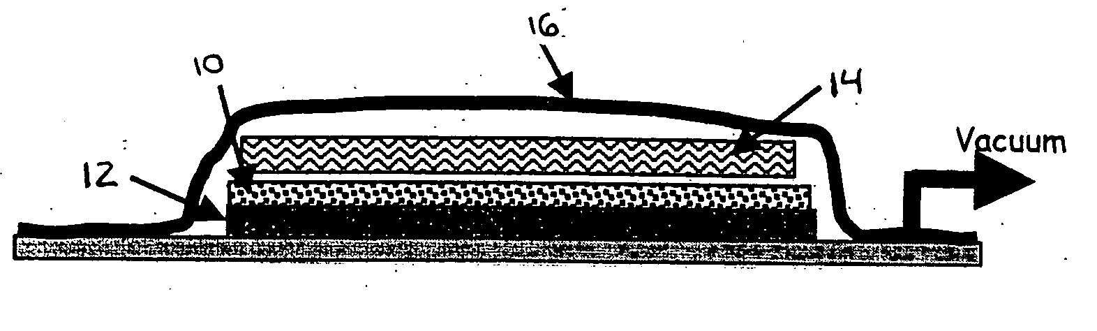
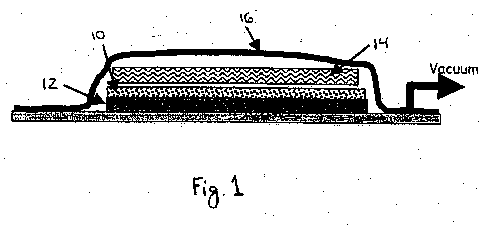
[0018] Nextel 440 cloth (3M Corporation) reinforced silica (SiO2) matrix CMC (designated S-N440). In this example, ceramic preforms were created by laying together plies of Nextel 440 cloth, desizing the lay-up at about 1200° F., inserting the desized lay-up into a cotton bag and taping the ends of the bag with polyterafluroethylene (PTFE) tape, such as Teflon® brand tape from DuPont. The preforms were then overlaid with ⅛-inch thick open weave material soaked with ceramic slurry, such as set forth in Example 1. The slurry for the S-N440 system includes sub-micron silica, a silica-yielding polymer, solvents and deflocculents as defined by U.S. Pat. No. 5,306,554. This sandwich was placed in a silicone vacuum bag and a vacuum of greater than about 20 in. Hg drawn for a period of greater than about 15 minutes to infiltrate the slurry into the ceramic preform. The slurry-infiltrated preforms were dried overnight in ambient air and then laminated at or above nominal laminating condition...


PUM

PropertyMeasurementUnit
temperatureaaaaaaaaaa

Abstract

Methods are provided for producing a ceramic matrix composite by slurry infiltration. The methods involve placing a desized ceramic cloth lay-up into a non-ceramic cloth bag, sealing the bag to form a bagged ceramic preform, infiltrating the bagged ceramic preform with a ceramic-containing slurry, and sintering the preform to convert the slurry to a ceramic while decomposing the non-ceramic bag. The methods of the present invention maximize slurry infiltration of the ceramic cloth tow bundle while minimizing damage to the ceramic cloth.

Description

FIELD OF THE INVENTION [0001] The invention concerns methods of producing a ceramic matrix composite by slurry infiltration. In particular, the invention concerns novel slurry infiltration methods of producing ceramic matrix composites (CMC). The methods of the present invention maximize slurry infiltration of the ceramic cloth tow bundle while minimizing damage to the ceramic cloth BACKGROUND OF THE INVENTION [0002] There are at least five known and current processes for forming CMCs using ceramic cloth. Those processes generally include: 1) prepregging, wherein ceramic cloth is run over a series of rollers and through tensioners, dipped into a slurry tank, dried in a tower, sandwiched between layers of plastic sheeting, and rolled onto a tube; 2) chemical vapor infiltration, wherein a preform of ceramic cloth plies is set inside a chemical vapor reactor, the preform is heated, and atoms or molecules in the form of vapor are deposited on and, hopefully, within the ceramic cloth; 3)...

Claims


Application Information

Patent Timeline
Patent Type & Authority Applications(United States)
IPC IPC(8): C03B29/00
CPCB32B18/00B32B2315/02C04B35/14C04B35/18C04B35/803C04B2235/5228C04B2235/5232C04B2235/602C04B2235/616C04B2235/96C04B2237/341C04B2237/38C04B35/63C04B35/63452C04B2235/656C04B2237/343C04B35/80
Inventor MILLARD, MICHAEL LEERICHARDSON, HORACE JR.
Owner GENERAL ELECTRIC CO
Why Eureka
Try Eureka