Protective railing

a technology of guardrails and railings, applied in the direction of shutters/movable grilles, buildings, constructions, etc., can solve the problems of letting the guardrails be opened and not obtaining true protection for a baby or a p

Inactive Publication Date: 2006-04-20
CHENG KUO HO
View PDF6 Cites 25 Cited by
  • Summary
  • Abstract
  • Description
  • Claims
  • Application Information

AI Technical Summary

Benefits of technology

[0005] The purpose of the invention is to offer a protective railing possible to be locked without fail to truly obtain protection for a baby or a pet (or pets).

Problems solved by technology

Anyway, this kind of locking the railing is not so sure to be locked by the latch, often not correctly inserted in the latch hole, letting the railing liable to be opened, not obtaining true protection for a baby or a pet.

Method used


Image

  • Protective railing
  • Protective railing
  • Protective railing

Examples


Embodiment Construction

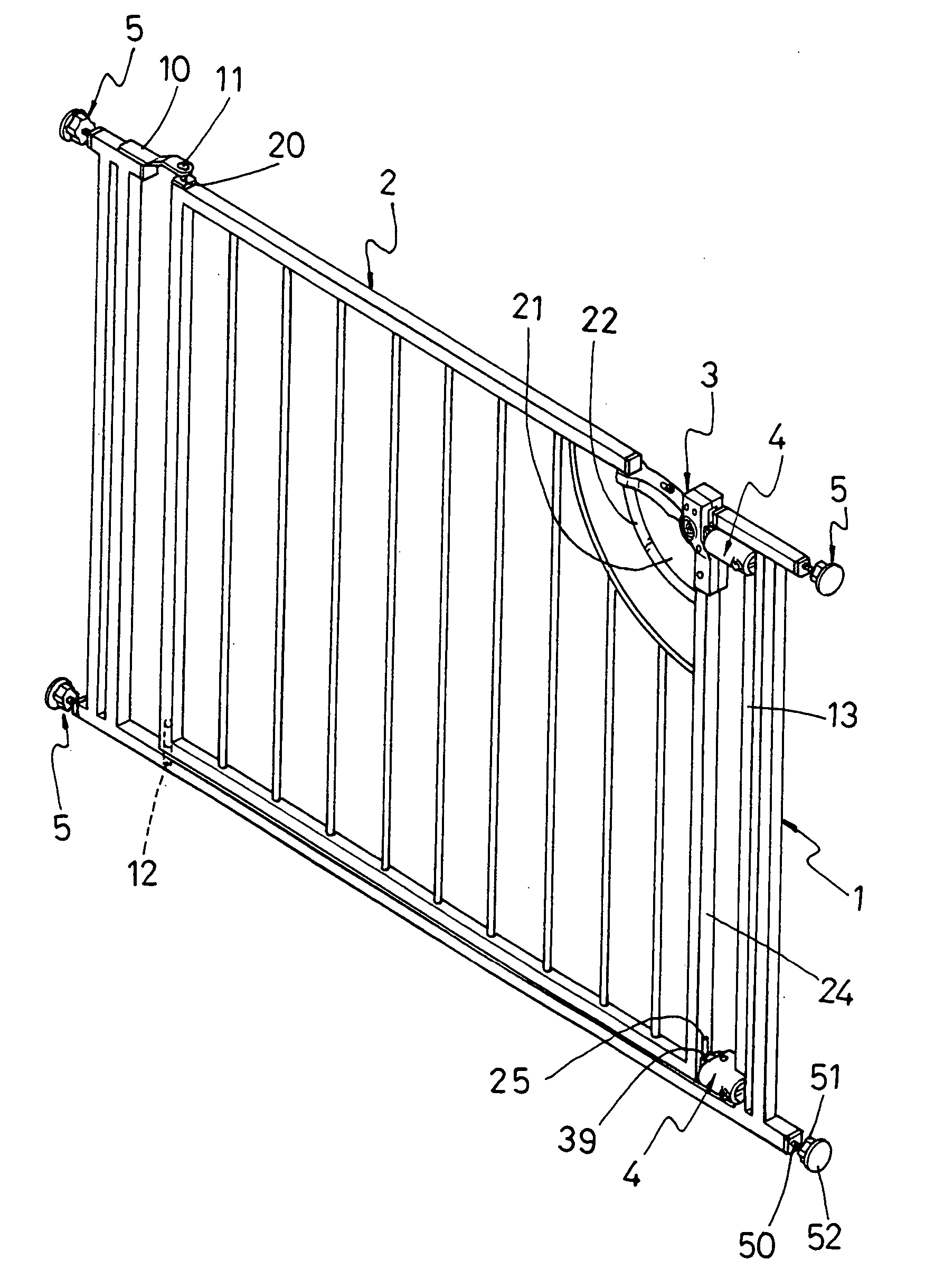
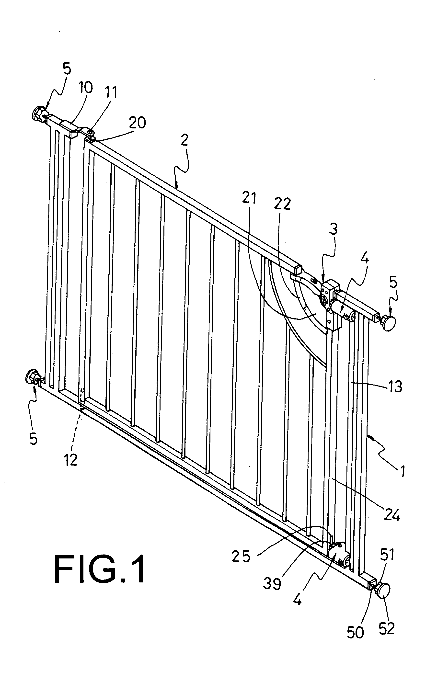
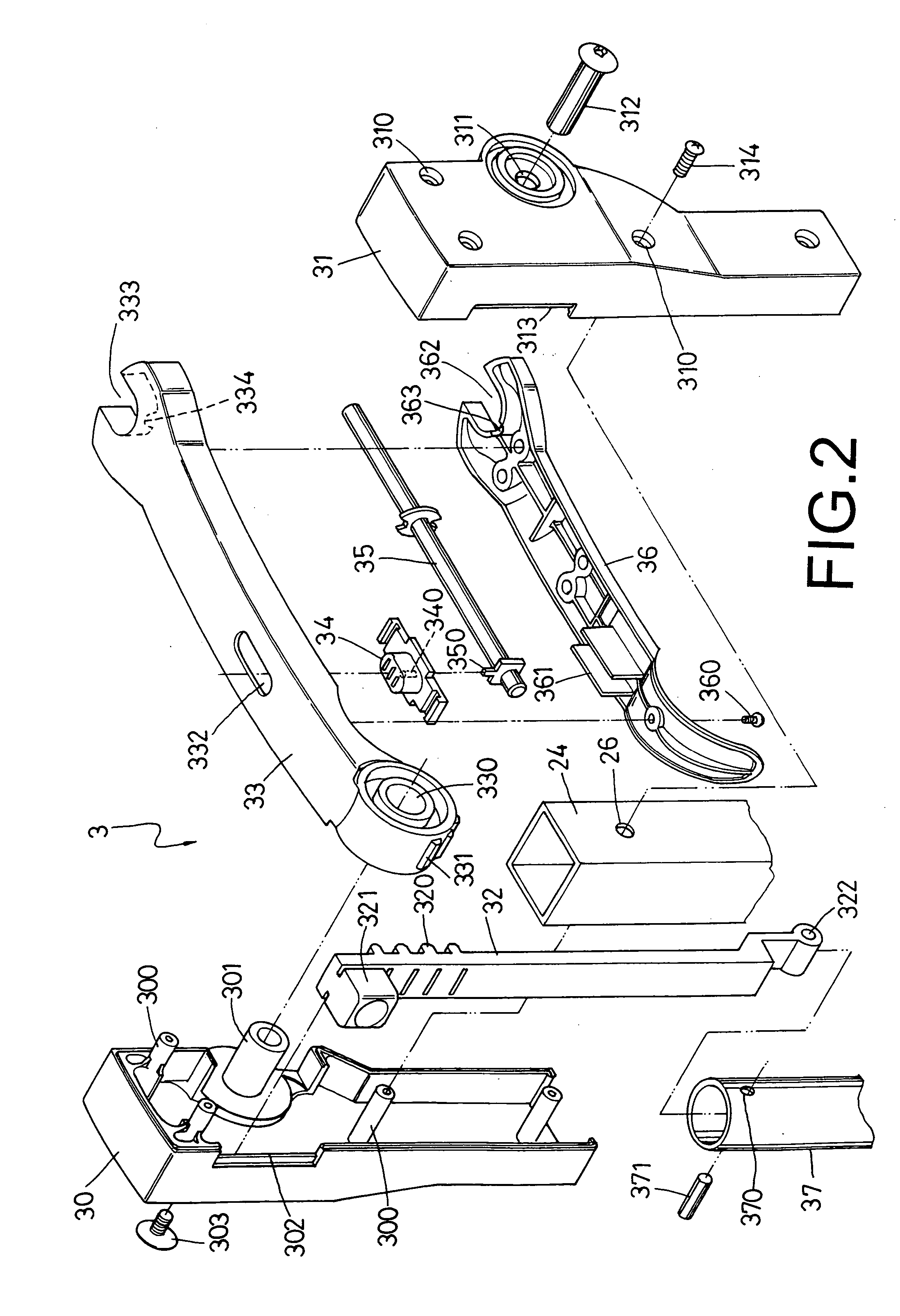
[0016] A preferred embodiment of a protective railing in the present invention, as shown in FIGS. 1, 2, 3 and 4, includes a frame 1, a railing body 2, a lockset 3, a fix unit 4 and plural position members 5 as main components combined together.

[0017] The frame 1 is U-shaped, having a pivotal base 10 on an upper side, a pivot 11 fixed on the pivotal base 10, a pivot 12 also fixed on a lower side to corresponding to the pivot 11.

[0018] The railing body 2 is fixed inside the frame 1, having a shaft hole 20 respectively in an upper side and a lower side for the pivots 11, 12 to extend in so as to combine one side of the railing body 2 pivotally with the frame 1, The railing body 2 further has an opening 21 in an upper section of one side, and a curved guide rod 22 fixed in the opening 21. The guide rod 22 has an insert hole 23, as shown in FIG. 6. The railing body 2 has a vertical side hollow rod 24 closing the opening 21, and the side rod 24 has a slot 25 formed in a lower end, and p...


PUM


Abstract

A protective railing includes a frame, a railing body, a lockset, two fix unit and plural position members. The position members secure the frame to a doorframe or in a passageway. If the railing body is to be opened, a push button on a grip is shifted to move a deadbolt inward to separate from an insert hole of the railing body, and then the grip is pressed down to move up a rack together with a connect tube, with a stop block of the rack and the connect tube separate from between two stoppers of the fix unit, unlocking the lock set to let the railing body opened. To lock the lockset, after the railing body is closed, the push button is shifted outward to move the deadbolt to insert in the insert hole of the raining body, finishing locking process.

Description

BACKGROUND OF THE INVENTION [0001] 1. Field of the Invention [0002] This invention relates to a protective railing, particularly to one consisting of a frame, a railing body, a lockset, a fix unit and plural position members. The position members secure the frame with a doorframe or in a passageway. If the railing body is wanted to be opened, a push button on a grip is shifted inward to force a deadbolt retreat inward and separate from an insert hole of the railing body. Then the grip is swung downward, moving up a rack and a connect tube to separate stop blocks of the rack and the connect tube from between two stop blocks of the fix unit so that the railing body may be opened. If the railing body is to be locked after closed, the push button of the grip is moved outward, shifting outward one end of the deadbolt to insert in the insert hole of the railing body, finishing locking the railing body. [0003] 2. Description of the Prior Art [0004] In order to prevent a baby or a pet from ...

Claims


Application Information

Patent Timeline
Patent Type & Authority Applications(United States)
IPC IPC(8): E04H17/16
CPCE06B9/04E06B2009/002
Inventor CHENG, KUO-HO
Owner CHENG KUO HO
Why Eureka
Try Eureka