Secondary battery module

a battery module and second battery technology, applied in the direction of current conducting connection, cell components, electrochemical generators, etc., can solve the problem of inconvenient manufacture of conventional battery modules b>1, and achieve the effect of stable fixed state, convenient and rapid manufacturing

a battery module and second battery technology, applied in the direction of current conducting connection, cell components, electrochemical generators, etc., can solve the problem of inconvenient manufacture of conventional battery modules b>1, and achieve the effect of stable fixed state, convenient and rapid manufacturing

US20060083980A1Active Publication Date: 2006-04-20LG ENERGY SOLUTION LTD

Image

  • Secondary battery module
  • Secondary battery module
  • Secondary battery module

Examples


Embodiment Construction

[0020] Now, a preferred embodiment of the present invention will be described in detail with reference to FIGS. 2 to 6.

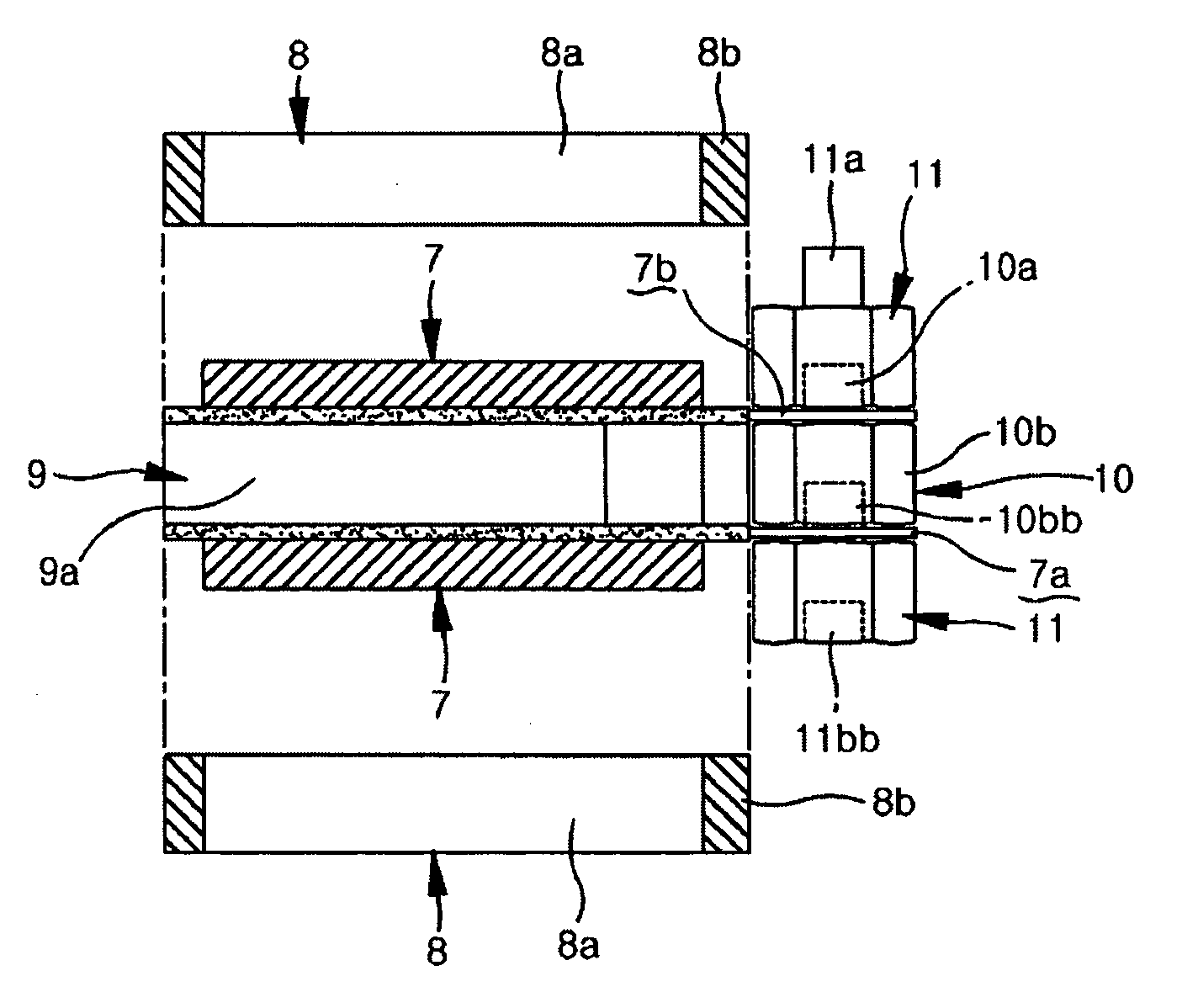
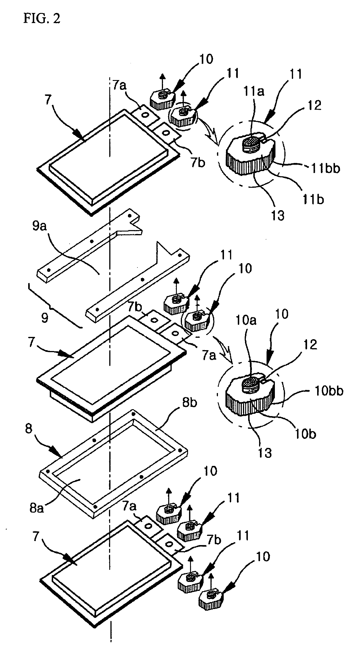
[0021]FIG. 2 is an exploded perspective view of a secondary battery module in accordance with the present invention.

[0022] As shown in FIG. 2, the secondary battery module of the present invention comprises at least two battery cells 7, each having a protruded surface and a leveled surface, arranged such that the protruded surfaces of the neighboring battery cells 7 face each other and the leveled surfaces of the neighboring battery cells 7 face each other, at least one fixing block 8 disposed along the edge of the protruded surface of the corresponding battery cell 7 for fixing the corresponding battery cell 7 and the neighboring battery cell 7 to each other, at least one air guide block 9 disposed along at least a part of the edge of the leveled surface of the corresponding battery cell 7 for discharging the heat generated from the corresponding battery cell 7 t...


PUM


Abstract

A secondary battery module comprises at least two battery cells laminated to a designated depth, in which an air guide block is interposed between leveled surfaces of the neighboring battery cells and a fixing block is interposed between protruded surfaces of the neighboring battery cells, the air guide blocks and the fixing blocks are fixed to each other using fasteners, and corresponding electrode terminals of the neighboring battery cells are interconnected in series by conductive and insulating connection members serving as bolts and nuts, thereby being conveniently installed in various industrial facilities and electric vehicles.

Description

FIELD OF THE INVENTION [0001] The present invention relates to a secondary battery module, and more particularly to a secondary battery module having at least two battery cells laminated to a designated depth, in which an air guide block is interposed between leveled surfaces of the neighboring battery cells and a fixing block is interposed between protruded surfaces of the neighboring battery cells, the air guide blocks and the fixing blocks are fixed to each other using fasteners, and corresponding electrode terminals of the neighboring battery cells are interconnected in series by conductive and insulating connection members serving as bolts and nuts, thereby being conveniently installed in various industrial facilities and electric vehicles. BACKGROUND OF THE INVENTION [0002] Generally, since the output of one unit battery is limited, a battery module comprising a plurality of battery cells is used in electric vehicles and leisure facilities requiring the large scale output. [00...

Claims


Application Information

Patent Timeline
20 Apr 2006
Publication
US20060083980A1
IPC
H01M10/50; H01M2/24; H01M50/502; H01M50/529; H01M50/553
CPC
H01M2/202; H01M2/30; H01M10/48; H01M10/5004; H01M10/5032; H01M10/5067; H01M10/5073; H01M10/6563
Inventors
CHOO, HYUN SUK; YU, JI SANG