Connector and connector assembly

Inactive Publication Date: 2006-04-20
SUMITOMO WIRING SYST LTD
View PDF4 Cites 18 Cited by
  • Summary
  • Abstract
  • Description
  • Claims
  • Application Information

AI Technical Summary

Benefits of technology

[0015] The detector preferably is at the standby position, and an operable portion of the detector contacts at least one auxiliary stopper of acc

Problems solved by technology

Thus, the detector cannot be pushed to the detecting position.
The construction of the accommodating portion for the above-described dete

Method used


Image

  • Connector and connector assembly
  • Connector and connector assembly
  • Connector and connector assembly

Examples


Embodiment Construction

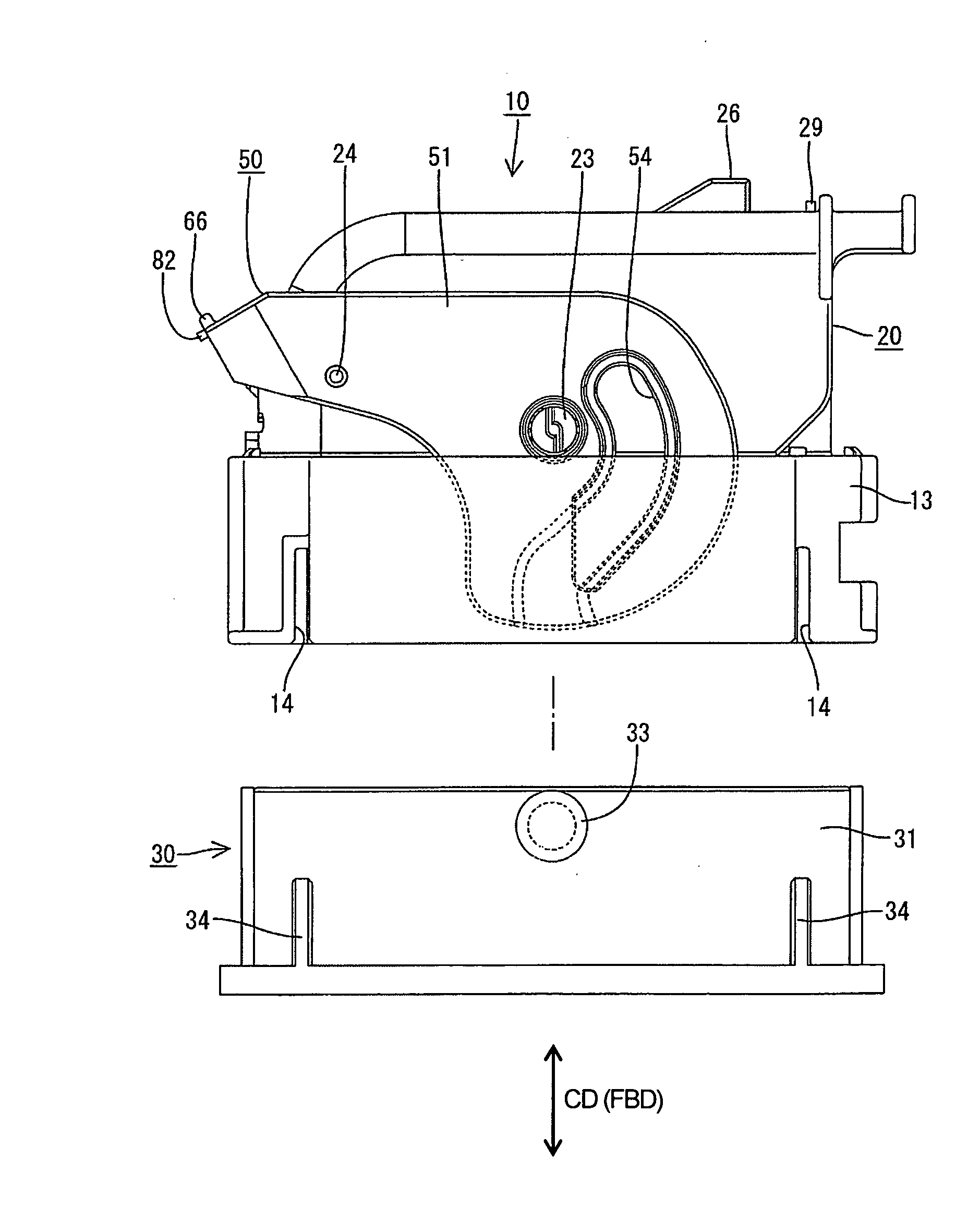
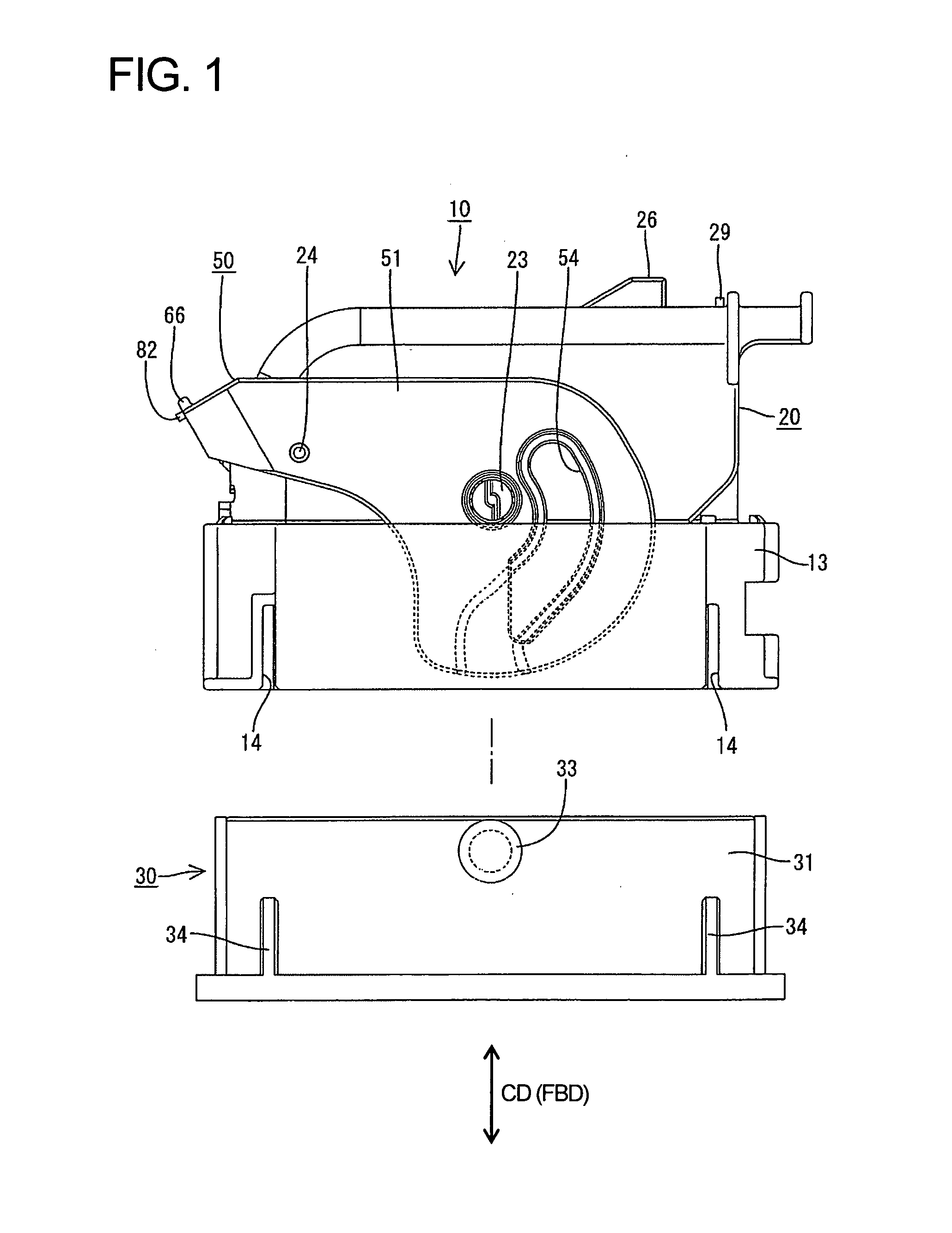
[0033] A lever-type connector according to the invention is described with reference to FIGS. 1 to 15. The connector is a lever-type connector with a female housing 10 and a male housing 30 that are connected along a connecting direction CD by rotating a lever 50 assembled into the female housing 10. In the following description, mating ends of the housings 10, 30 are referred to as the front and the left side in FIG. 1 is referred to as upper side concerning vertical direction.

[0034] The male housing 30 is made e.g. of a synthetic resin and has a receptacle 31 in the form of a substantially rectangular tube that opens forwardly. Male terminal fittings (not shown) are mounted through the back wall of the receptacle 31, and the leading ends of the male terminal fittings project into the receptacle 31. Cam pins 33 project in intermediate positions near the front end of the outer surface of each of the left and right walls of the male housing 30, as shown in FIG. 1. Further, guide rib...


PUM


Abstract

A lever (50) is mounted rotatably on a female housing (10). A resiliently deformable detector (80) is so assembled into the lever (50) and is movable between a standby position and a detecting position. The detector (80) contacts a stopper (70) in an accommodating portion (60) of the lever (50) when the female and male housings (10, 30) are not yet properly connected to prevent the lever (50) from being pushed to the detecting position. However, the detector (80) contacts an unlocking projection (29) on the female housing (10) and deforms away from the stopper (70) when the housings (10, 30) reach a properly connected state. As a result, the detector (80) can be pushed to the detecting position. An ability to move the detector (80) to the detecting position indicates that the housings (10, 30) are connected properly.

Description

BACKGROUND OF THE INVENTION [0001] 1. Field of the Invention [0002] The invention relates to a connector and to a connector assembly with a function of detecting a connected state. [0003] 2. Description of the Related Art [0004] Japanese Unexamined Patent Publication No. 2002-141145 discloses a connector that can detect a connected state. This connector has male and female housings that are connectable with one another. The female housing has a lock arm that is deformed in the process of connecting the two housings and is resiliently restored when the housings are connected properly to engage the male housing. A detector is assembled into the female housing and is movable between a standby position where the detector is retracted from a deformation space for the lock arm and a detecting position where the detector is in the deformation space. The detector contacts the lock arm in the deformation space if an attempt is made to push the detector from the standby position to the detect...

Claims


Application Information

Patent Timeline
IPC IPC(8): H01R13/62
CPCH01R13/62938H01R13/641
Inventor OHARA, KOJI
Owner SUMITOMO WIRING SYST LTD
Why Eureka
Try Eureka