

Method and system for providing referential integrity constraints
- Summary
- Abstract
- Description
- Claims
- Application Information
AI Technical Summary
Benefits of technology
Problems solved by technology
Method used
Image

Examples
Embodiment Construction
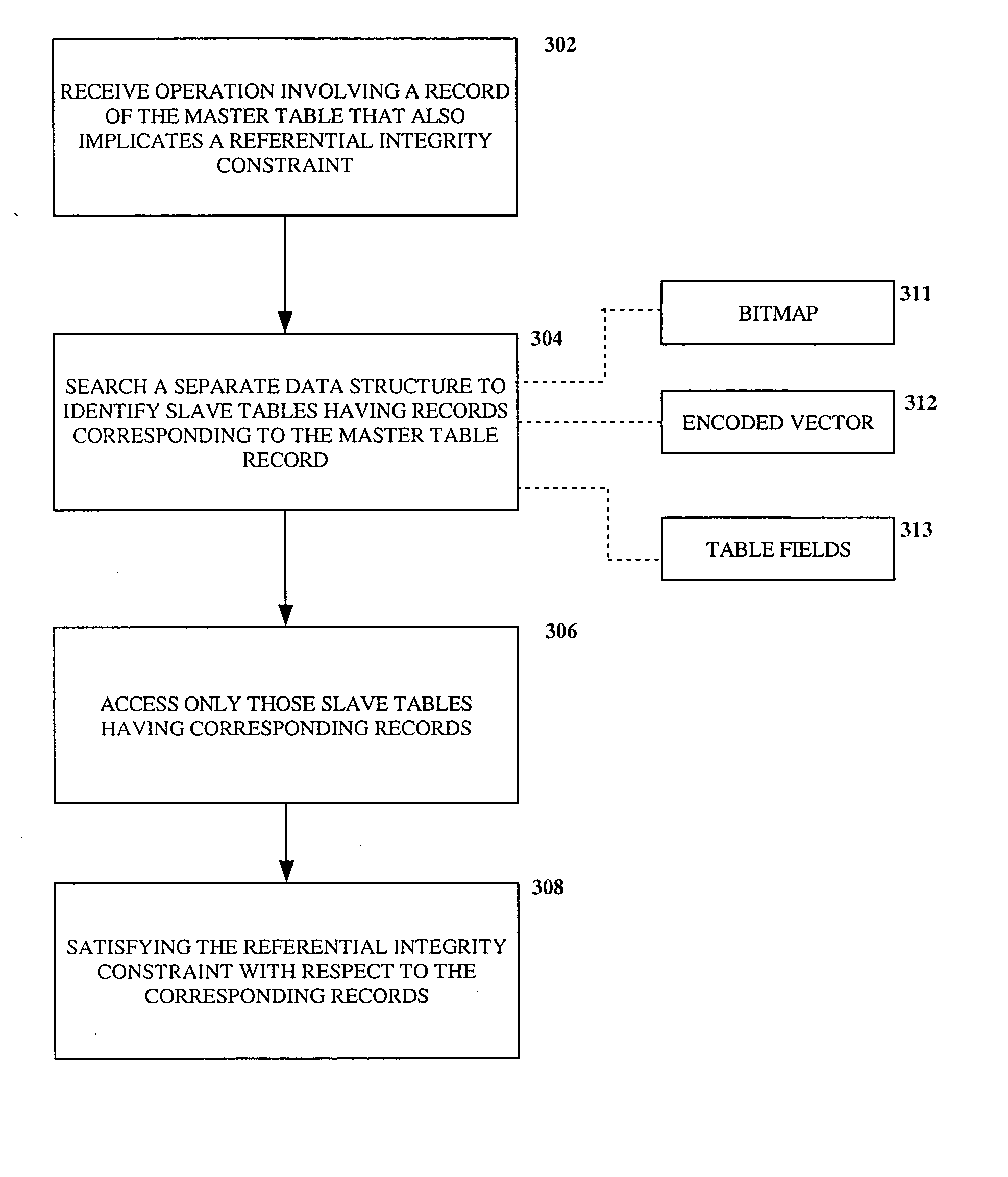
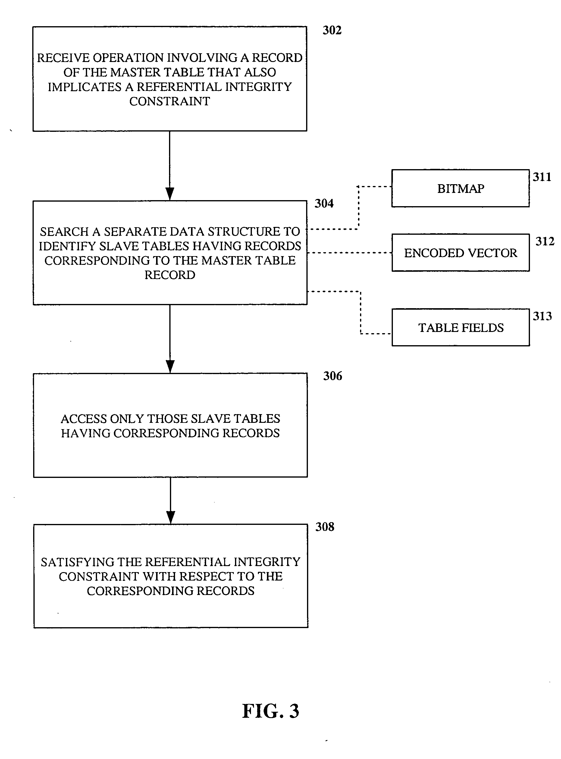
[0016] As mentioned above, the embodiments discussed hereinafter utilize a database engine and data structures that support identifying slave tables that have records needing to be acted upon due to referential integrity constraints. Instead of reading each related slave table and searching for related records, the data structure provides this information in a compact and easy to use format. A specific implementation of such a database engine and monitoring tool capable of supporting this functionality in a manner consistent with the invention will be discussed in greater detail below. However, prior to a discussion of such a specific implementation, a brief discussion will be provided regarding an exemplary hardware and software environment within which such an implementation may reside.
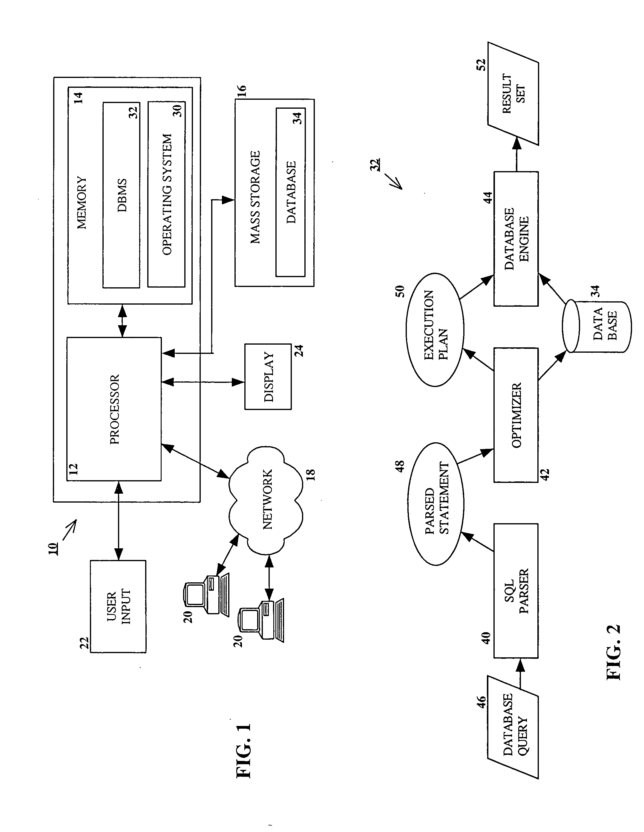
[0017] Turning now to the Drawings, wherein like numbers denote like parts throughout the several views, FIG. 1 illustrates an exemplary hardware and software environment for an apparatus 10 suitab...
PUM
 Abstract
Description
Claims
Application Information