

Aircraft passenger accommodation unit with deployable bed
- Summary
- Abstract
- Description
- Claims
- Application Information
AI Technical Summary
Benefits of technology
Problems solved by technology
Method used
Image

Examples
Embodiment Construction
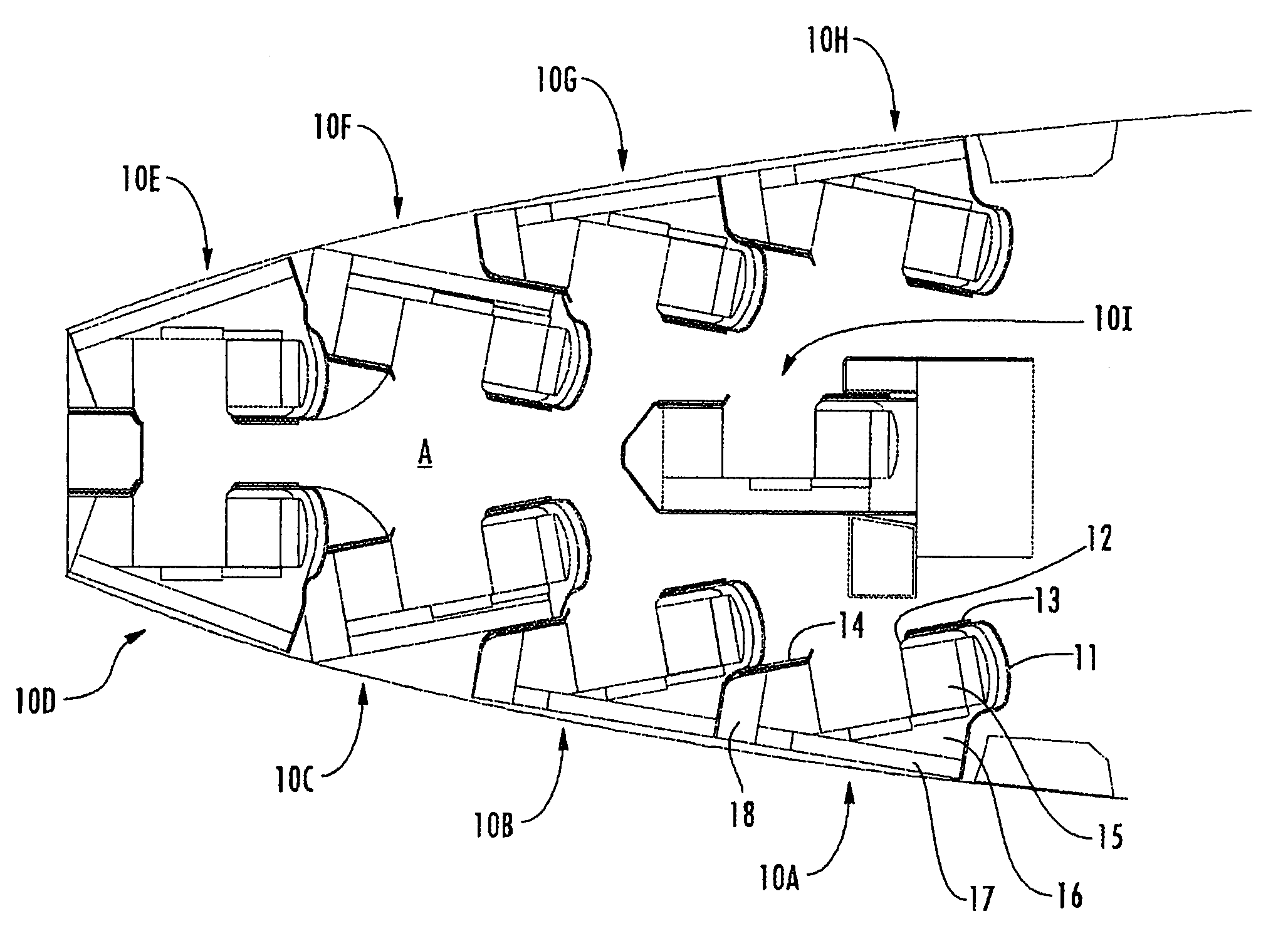
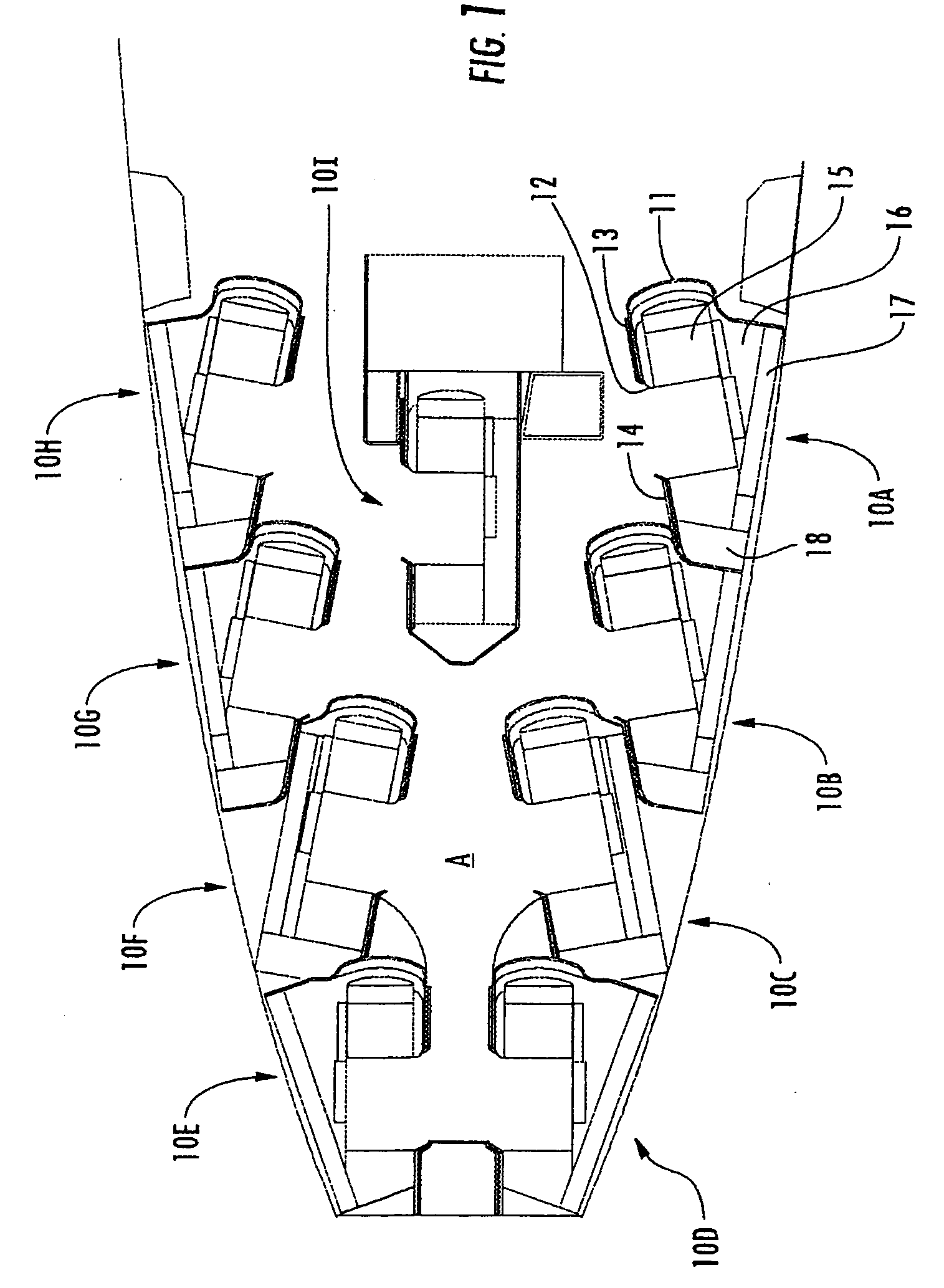
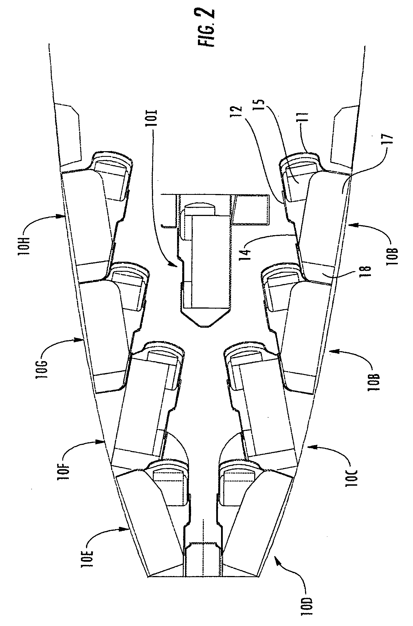
[0045] Referring now specifically to the drawings, an aircraft first class cabin “A” with 9 individual passenger units 10, identified individually as accommodation units 10A-I, according to an embodiment of the invention is shown in FIGS. 1 and 2. As is shown, the accommodation units 10A-I are arranged in an irregular, staggered, configuration to occupy the minimum amount of space and accommodate the forward narrowing width of the cabin “A.” Six of the accommodation units 10, 10A-C and F-H, are arrayed in two rows of three each, with the forward end of the units adjacent the sides of the aircraft and the aft end angled inwardly. The two forwardmost accommodation units 10, 10D-E, are positioned generally parallel to the longitudinal axis of the aircraft fuselage, as is the ninth accommodation unit, 10I, which is positioned both parallel to and centered on the longitudinal axis of the aircraft fuselage. The arrangement and number of accommodation units 10 can vary based on the area an...
PUM
 Abstract
Description
Claims
Application Information