
Seat assembly with ventilation system utilizing venturi effect to multiply air flow

a seat and ventilation system technology, applied in the direction of chairs, seating arrangements, aircraft crew accommodation, etc., can solve the problems of seat construction, seat discomfort of aircraft seats and other vehicle seats

Active Publication Date: 2021-02-11
BE AEROSPACE INCORPORATED
View PDF3 Cites 11 Cited by
  • Summary
  • Abstract
  • Description
  • Claims
  • Application Information

AI Technical Summary

Benefits of technology

The patent text describes a ventilated seat assembly for aircraft passengers that includes a cushion assembly with Venturi tubes positioned to direct airflow through the cushion assembly. The assembly includes an air compressor, a manifold assembly, and a conduit network that connects the manifold assembly with the Venturi tubes. The controller is operable to activate the air compressor and the manifold assembly to cause the compressed air to flow through the conduit network to the Venturi tubes. The assembly can be positioned in the backrest or seat bottom, and the airflow can be directed to specific regions of the cushion assembly, such as the lower backrest region, upper backrest region, lumbar region, side bolster region, or headrest region. The technical effects of this invention include improved cooling and ventilation for the passenger seat, as well as improved airflow and comfort for the passenger.

Problems solved by technology

Aircraft seats and other vehicle seats can become uncomfortable over time, particularly when a passenger remains in a constant sitting position.
While premium seating classes are configured to maximize comfort and seat adjustability, the space and cost constraints of economy classes limit seat constructions to a fixed seat bottom with limited backrest recline.
In aircraft, because of the large number of seats, limited capacity of the vehicle air conditioning system, and constraints that do not allow for a separate air conditioning system dedicated for seat cooling, typically only a limited number of premium class seats enjoy the benefit of cooling, if any.

Method used


Image

  • Seat assembly with ventilation system utilizing venturi effect to multiply air flow
  • Seat assembly with ventilation system utilizing venturi effect to multiply air flow
  • Seat assembly with ventilation system utilizing venturi effect to multiply air flow

Examples


Embodiment Construction

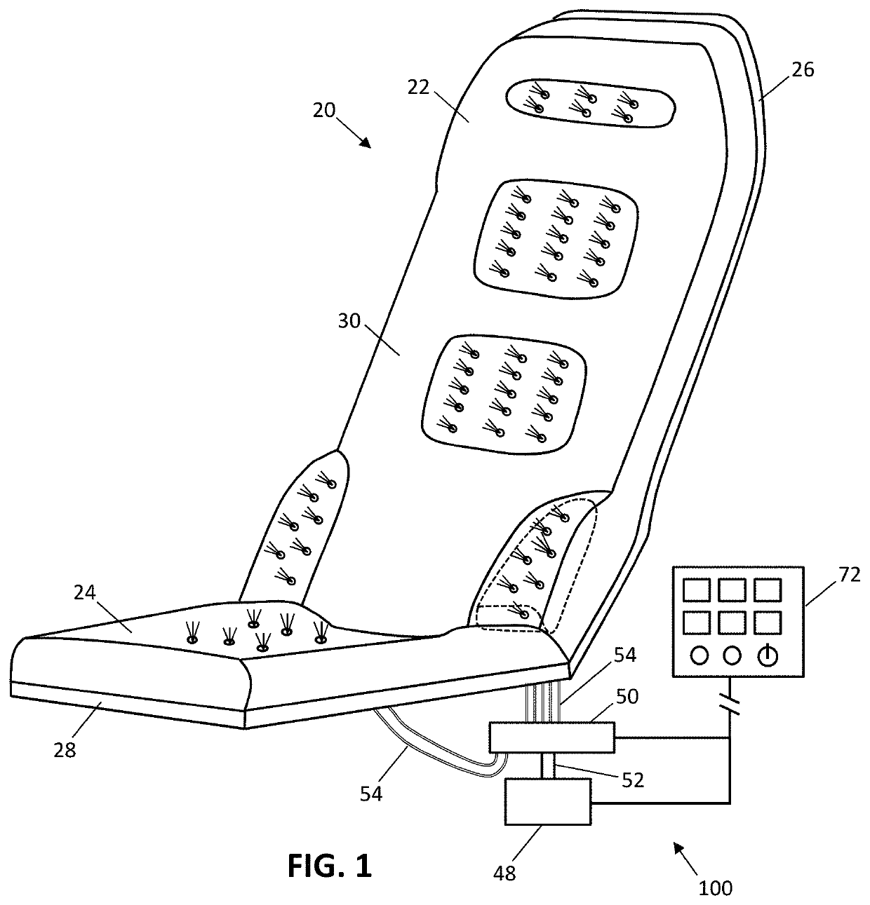
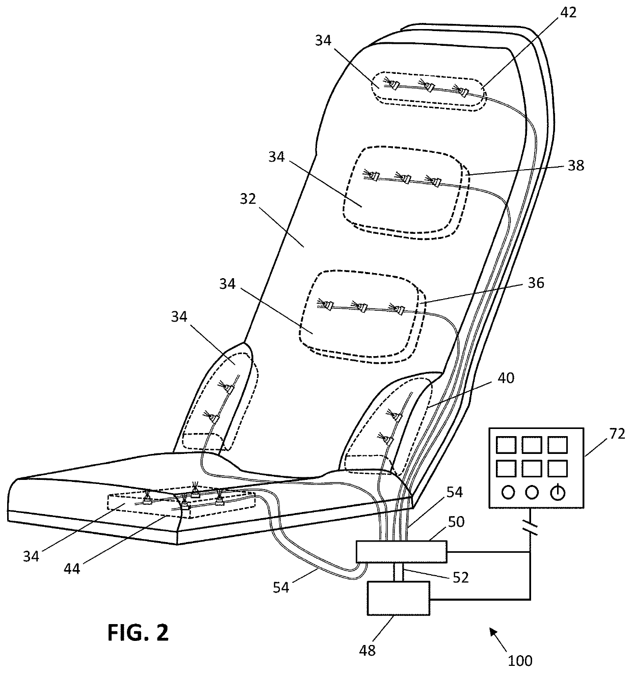
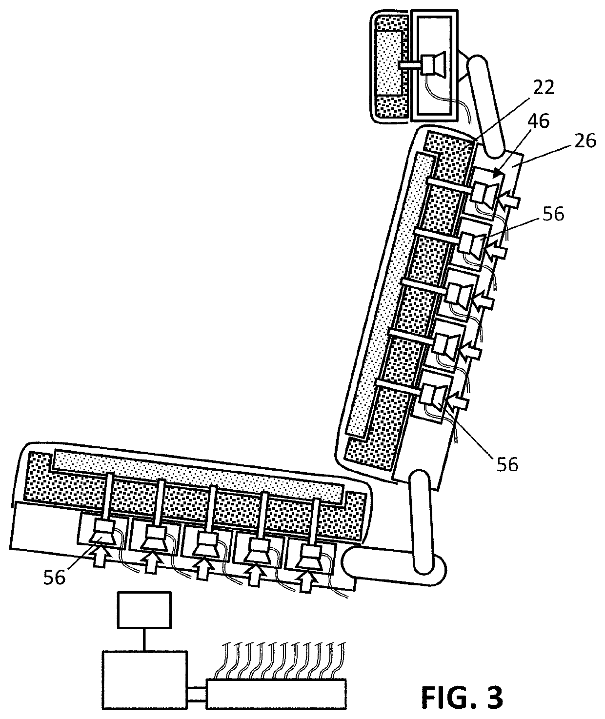
[0025]The description set forth below in connection with the appended drawings is intended to be a description of various, illustrative embodiments of the disclosed subject matter. Specific features and functionalities are described in connection with each illustrative embodiment; however, it will be apparent to those skilled in the art that the disclosed embodiments may be practiced without each of those specific features and functionalities. The aspects, features and functions described below in connection with one embodiment are intended to be applicable to the other embodiments described below except where expressly stated or where an aspect, feature or function is incompatible with an embodiment.

[0026]Referring to the drawing figures, the inventive concepts disclosed herein are directed to passenger seat constructions including seat ventilation systems for improving seat comfort. The seat constructions are not limited to any seat type and therefore find widespread application i...


PUM


Abstract

A ventilated seat assembly such as an aircraft passenger seat including a cushion assembly supported by a structural element, a plurality of Venturi tubes positioned to direct a flow of air through the cushion assembly, an air compressor supplying compressed air, a manifold assembly coupled in fluid communication with the air compressor, a conduit network fluidly coupling the manifold assembly with the plurality of Venturi tubes, and a controller for activating the air compressor and actuating the manifold assembly. Supplying a small volume of pressurized air to the Venturi tubes induces a larger flow of ambient air and a multiplied air effect to ventilate the passenger seat.

Description

BACKGROUND[0001]Aircraft seats and other vehicle seats can become uncomfortable over time, particularly when a passenger remains in a constant sitting position. To alleviate discomfort, seat manufacturers provide adjustability in the seat. In aircraft, seats may adjust from upright during taxi, takeoff and landing to reclined in-flight to achieve a more comfortable sitting position. While premium seating classes are configured to maximize comfort and seat adjustability, the space and cost constraints of economy classes limit seat constructions to a fixed seat bottom with limited backrest recline. Because the sitting position is essentially the same in an economy class seat whether the seat is upright or reclined, pressure points and hot spots tend to form quickly and remain the same throughout the duration of the flight.[0002]Another way to alleviate seat discomfort is to heat or cool the seat. Heating typically involves embedding an element in the seat that is electrically activate...

Claims


Application Information

Patent Timeline
Patent Type & Authority Applications(United States)
IPC IPC(8): B64D11/06A47C7/74
CPCB64D11/0626A47C7/744B60N2/56B60N2/5657B60N2/5628B60N2/5635B60N2/5642
Inventor WILSON, CHRISTOPHERSTAHL, PETER A.BUNEA, CATALIN
Owner BE AEROSPACE INCORPORATED
Learn More