AI technical title is built by Patsnap AI team. It summarizes the technical point description of the patent document.
a technology of synchronized strobes and alarm systems, applied in the direction of electric transmission signalling systems, visible signalling systems, electric signalling details, etc., can solve problems such as reported epileptic seizures in some people, and achieve the effect of avoiding overcharging of capacitors
Inactive Publication Date: 2006-04-27
ADT SERVICES
View PDF0 Cites 25 Cited by
Summary
Abstract
Description
Claims
Application Information
AI Technical Summary
This helps you quickly interpret patents by identifying the three key elements:
Problems solved by technology
Method used
Benefits of technology
Benefits of technology
[0008] In order to avoid overcharging of the capacitor as a strobe waits for the firing signal, each strobe further includes a voltage sensor for disabling the charging circuit when the capacitor reaches a firing voltage level.
Problems solved by technology
Unfortunately, the strobes at the higher intensity levels have been reported to trigger epileptic seizures in some people.
Method used
Image
Click on the blue label to locate the original text in one second.
Reading with bidirectional positioning of images and text.
Examples
Embodiment Construction
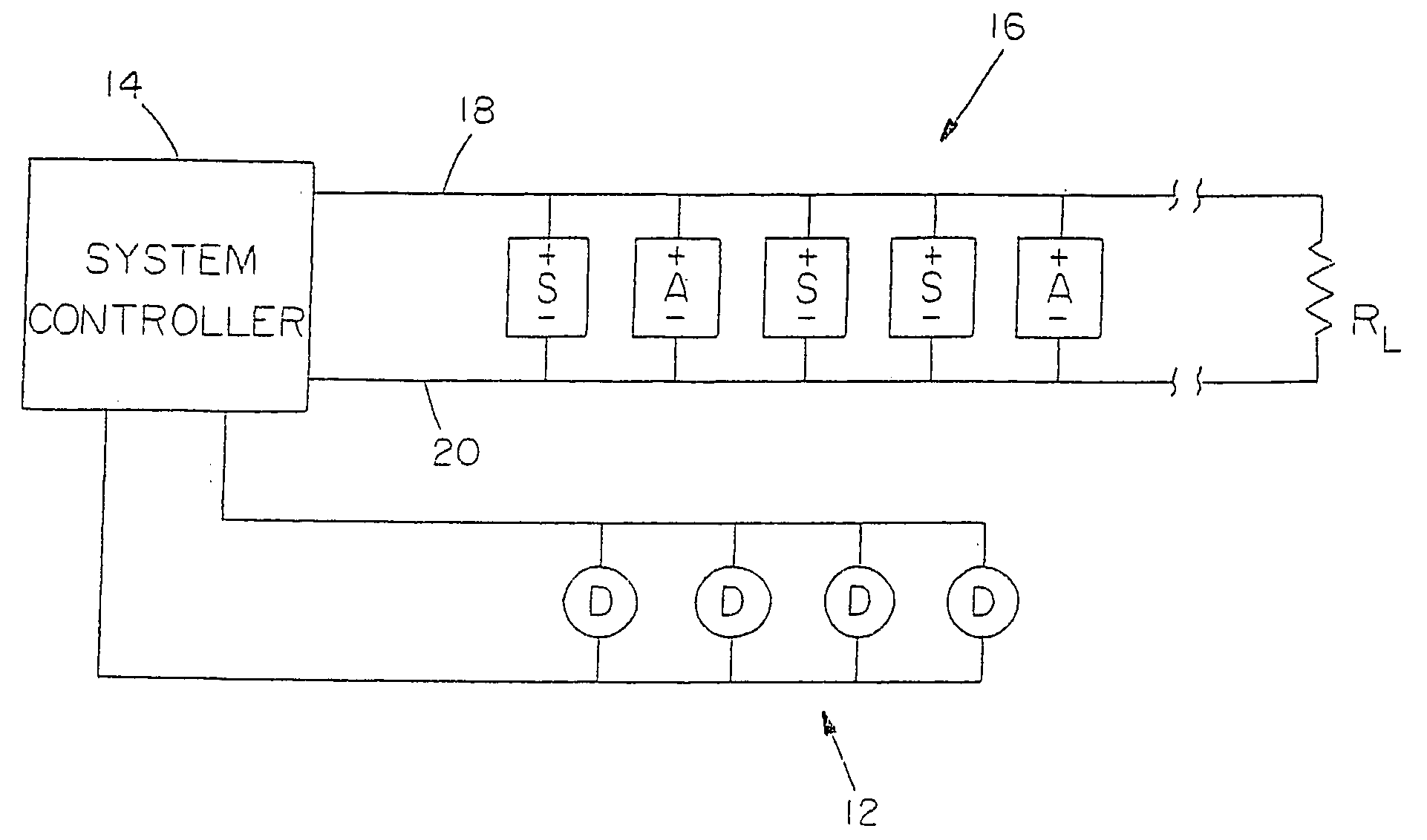
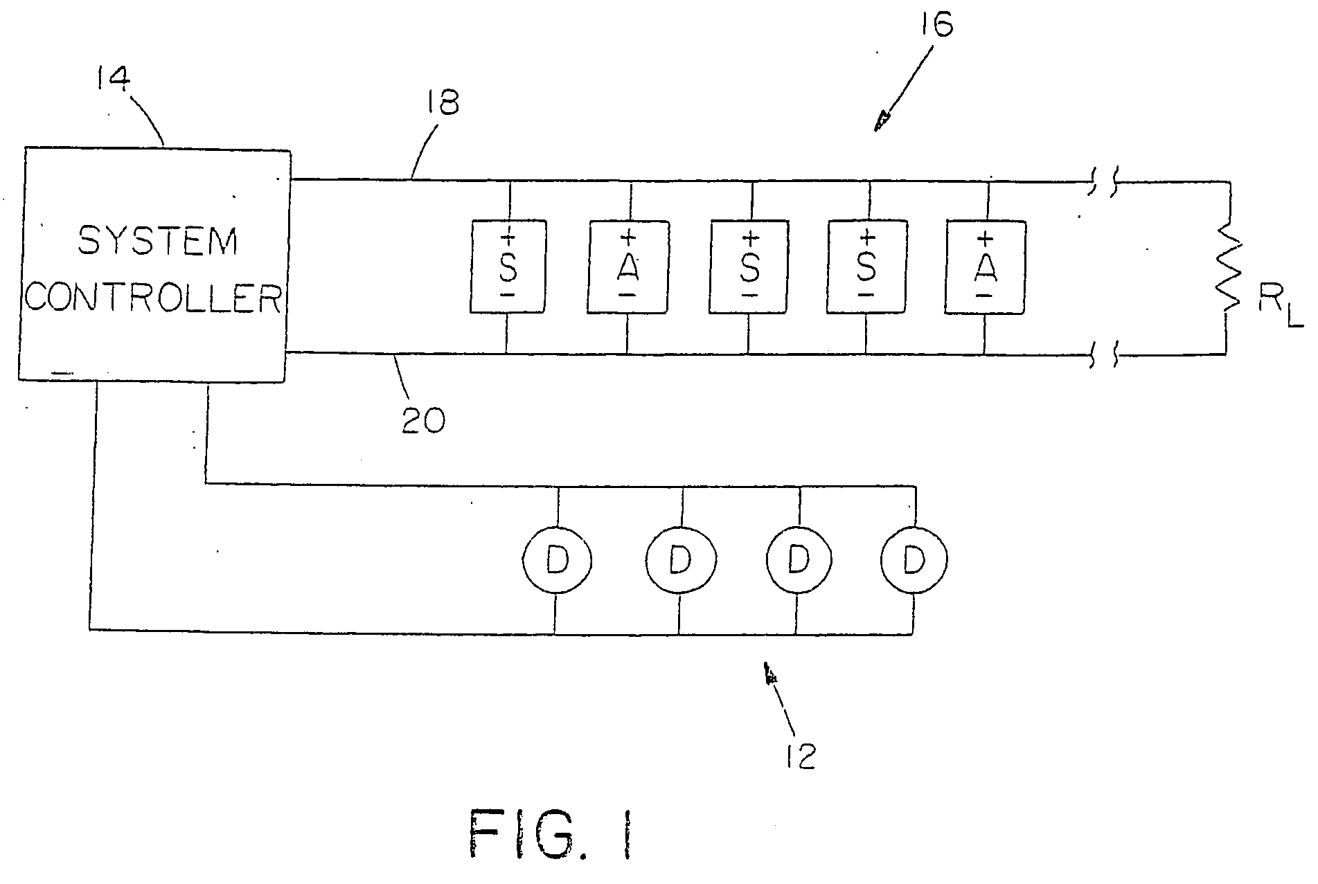
[0014] A system embodying the present invention is illustrated in FIG. 1. As in a conventional alarm system, the system includes one or more detector networks 12 having individual fire detectors D which are monitored by a system controller 14. When an alarm condition is sensed, the system controller signals the alarm through at least one network 16 of alarm indicators. The alarm indicators may include any variety of audible alarms A and light strobe alarms S. As shown, all of the alarms are coupled across a pair of power lines 18 and 20, and the lines 18 and 20 are terminated at a resistance RL.
[0015] Each of the alarms A and S includes a rectifier at its input which enables it to be energized with only one supply polarity as indicated. When there is no alarm condition, the network 16 may be monitored by applying a reverse polarity DC voltage across the network. Specifically, line 20 would be positive relative to line 18. Due to the rectifiers within the alarm devices, no alarm wou...
PUM
Abstract
In a building fire alarm system, the light strobes of a network of strobes are synchronized to flash simultaneously. Each strobe has a charging circuit to charge a capacitor which discharges through a flash tube. Once a capacitor is charged, the charging circuit is disabled. A synchronization pulse is applied through common power lines to trigger discharge of each strobe capacitor through the flash tube followed by recharging of the capacitor.
Description
RELATED APPLICATIONS [0001] This is a Continuation Application of U.S. application Ser. No. 10 / 948,092, filed Sep. 23, 2004, which is a Continuation Application of U.S. application Ser. No. 10 / 799,445, filed Mar. 12, 2004, which is a Continuation Application of U.S. application Ser. No. 10 / 642,113, filed Aug. 15, 2003, which is a Continuation Application of U.S. application Ser. No. 10 / 352,374, filed Jan. 27, 2003, which is a Continuation Application of U.S. application Ser. No. 10 / 211,935 filed Aug. 1, 2002, which is a Continuation Application of U.S. application Ser. No. 10 / 040,259 filed Jan. 2, 2002, which is a Continuation Application of U.S. application Ser. No. 09 / 709,081 filed Nov. 8, 2000, which is a Continuation Application of U.S. application Ser. No. 08 / 996,567 filed Dec. 23, 1997, now U.S. Pat. No. 6,741,164, which is a Divisional Application of U.S. application Ser. No. 08 / 682,140 filed Jul. 17, 1996, now U.S. Pat. No. 5,886,620, which is a Continuation Application of U...
Claims
Application Information
Patent Timeline
Application Date:The date an application was filed.
Publication Date:The date a patent or application was officially published.
First Publication Date:The earliest publication date of a patent with the same application number.
Issue Date:Publication date of the patent grant document.
PCT Entry Date:The Entry date of PCT National Phase.
Estimated Expiry Date:The statutory expiry date of a patent right according to the Patent Law, and it is the longest term of protection that the patent right can achieve without the termination of the patent right due to other reasons(Term extension factor has been taken into account ).
Invalid Date:Actual expiry date is based on effective date or publication date of legal transaction data of invalid patent.
Patent Type & AuthorityApplications(United States)

