
Apparatus and method for boosting signals from a signal-generating or modifying device

a signal-generating or modifying device and apparatus technology, applied in the direction of functional valve types, instruments, transportation and packaging, etc., can solve the problems of affecting the stability and overall handling of the vehicle, and affecting the operation of the vehicle. , to achieve the effect of improving the pumping of air into the tir

Inactive Publication Date: 2007-08-07
AMERICAN VEHICULAR SCI
View PDF11 Cites 16 Cited by
  • Summary
  • Abstract
  • Description
  • Claims
  • Application Information

AI Technical Summary

Benefits of technology

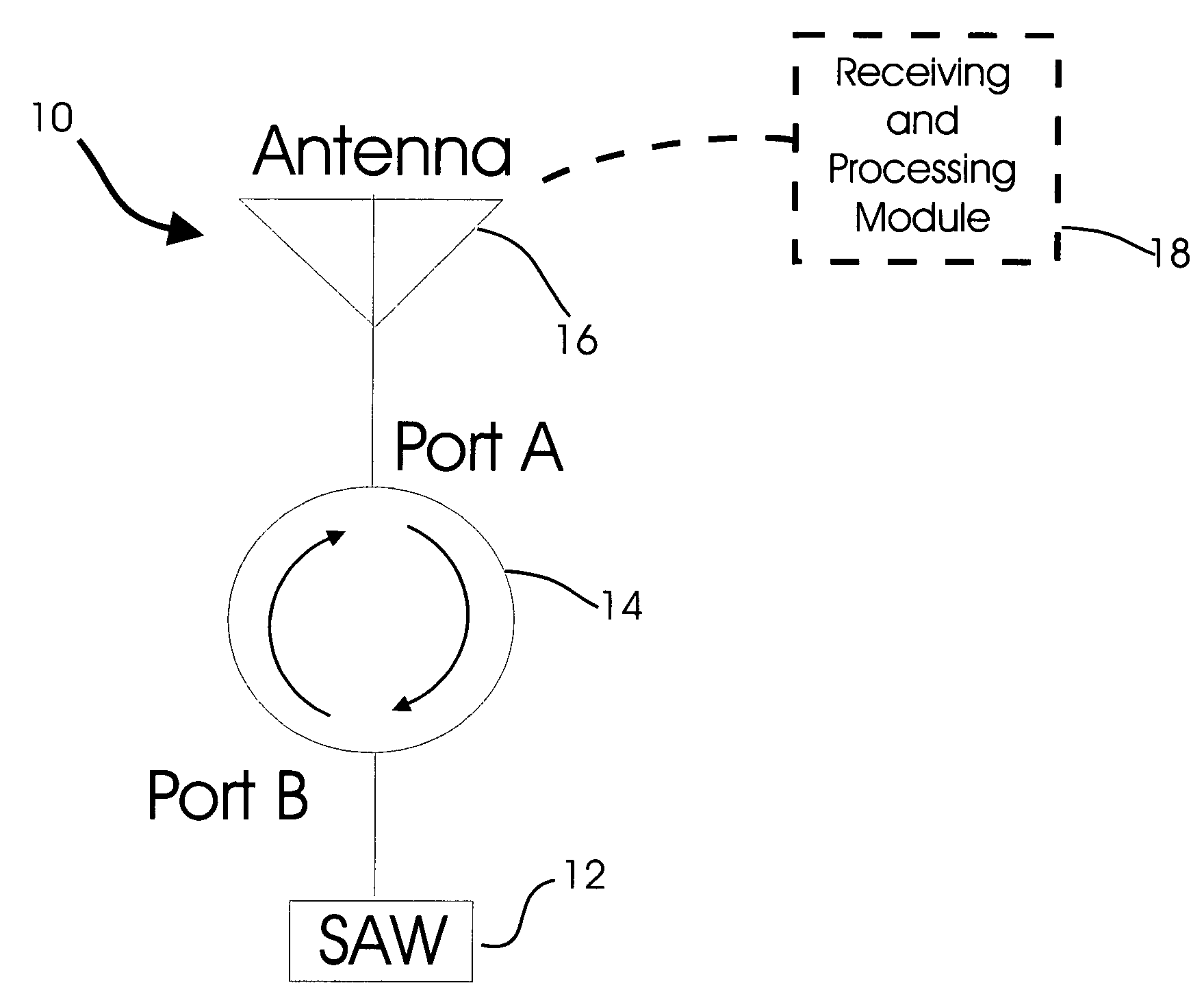
[0053]It is another object of the present invention to provide a new and improved arrangement including a SAW device and which provides a boost for a signal to and / or from a signal-generating, signal-receiving, or signal-activated sensor such as a SAW device or RFID tag.
[0062]The energy-supply module may also comprise an over-charge protector to prevent overcharging of the capacitor, such as a Zener diode arranged in a parallel with the capacitor.
[0065]To improve the pumping of air into the tire, the housing an also include a second fluid-receiving chamber with the piston rod being movable therein. A second spring is compressed by the mass upon movement thereof in an opposite direction from a direction in which the first spring is compressed by the mass. A second inlet valve is arranged in the housing and leads from ambient atmosphere to the second chamber. A second tube is adapted to connect to a nipple or other inlet of the tire. A second exhaust valve is arranged in the housing and provides a flow connection from the second chamber to the second tube.

Problems solved by technology

Recent studies in the United States conducted by the Society of Automotive Engineers show that low tire pressure causes about 260,000 accidents annually.
Another finding is that about 75% of tire failures each year are preceded by slow air leaks or inadequate tire inflation.
Nissan, for example, warns that incorrect tire pressures can compromise the stability and overall handling of a vehicle and can contribute to an accident.
Additionally, most non-crash auto fatalities occur while drivers are changing flat tires.
Thus, tire failures are clearly a serious automobile safety problem that requires a solution.
When under-inflated, a tire tends to flex its sidewall more, increasing its rolling resistance which decreases fuel economy.
The extra flex also can create excessive heat in the tire that can shorten its service life.
The leak will be minor as long as the nail is trapped.
Incidents of sudden pressure loss are potentially the most dangerous for drivers and account for about 15% of all cases.
A defective or worn tire can lose pressure at a more rapid rate.
Low tire pressure can also lead to damage to both the tires and wheels.
One of the reasons is that today's radial tire is hard to judge visually because the sidewall flexes even when properly inflated.
Despite all the recent press about keeping tires properly inflated, new research shows that most drivers do not know the correct inflation pressure.
The National Highway Traffic Safety Administration estimates that at least one out of every five tires is not properly inflated.
The problem is exacerbated with the new run-flat tires where a driver may not be aware that a tire is flat until it is destroyed.
A variety of mechanical problems including a bad wheel bearing or a “dragging” brake can cause the tire to heat up and fail.
In addition, as may have been a contributing factor in the Firestone case, substandard materials can lead to intra-tire friction and a buildup of heat.
The use of re-capped or over-loaded truck tires is another example of heat caused failure as a result of intra-tire friction.
An overheated tire can fail suddenly without warning.
Thus, as with other safety products such as airbags, competition to meet customer demands will soon drive this market.
The device disclosed, however, contains a battery and electronics and is not a SAW device.
Other patents disclose the placement of an electronic device in the sidewall or opposite the tread of a tire but they do not disclose either an accelerometer or a surface acoustic wave device.
In the use of SAW sensors for vehicles, one problem which arises is that the vibrations of the vehicle can interfere with or create excessive noise in the signals provided by the SAW sensor in view of the generally low strength of the signal from the SAW sensor.
The operating frequency of SAW devices has previously been limited to less than about 500 MHz due to manufacturing problems.

Method used


Image

  • Apparatus and method for boosting signals from a signal-generating or modifying device
  • Apparatus and method for boosting signals from a signal-generating or modifying device
  • Apparatus and method for boosting signals from a signal-generating or modifying device

Examples


Embodiment Construction

1. Boosting Signals

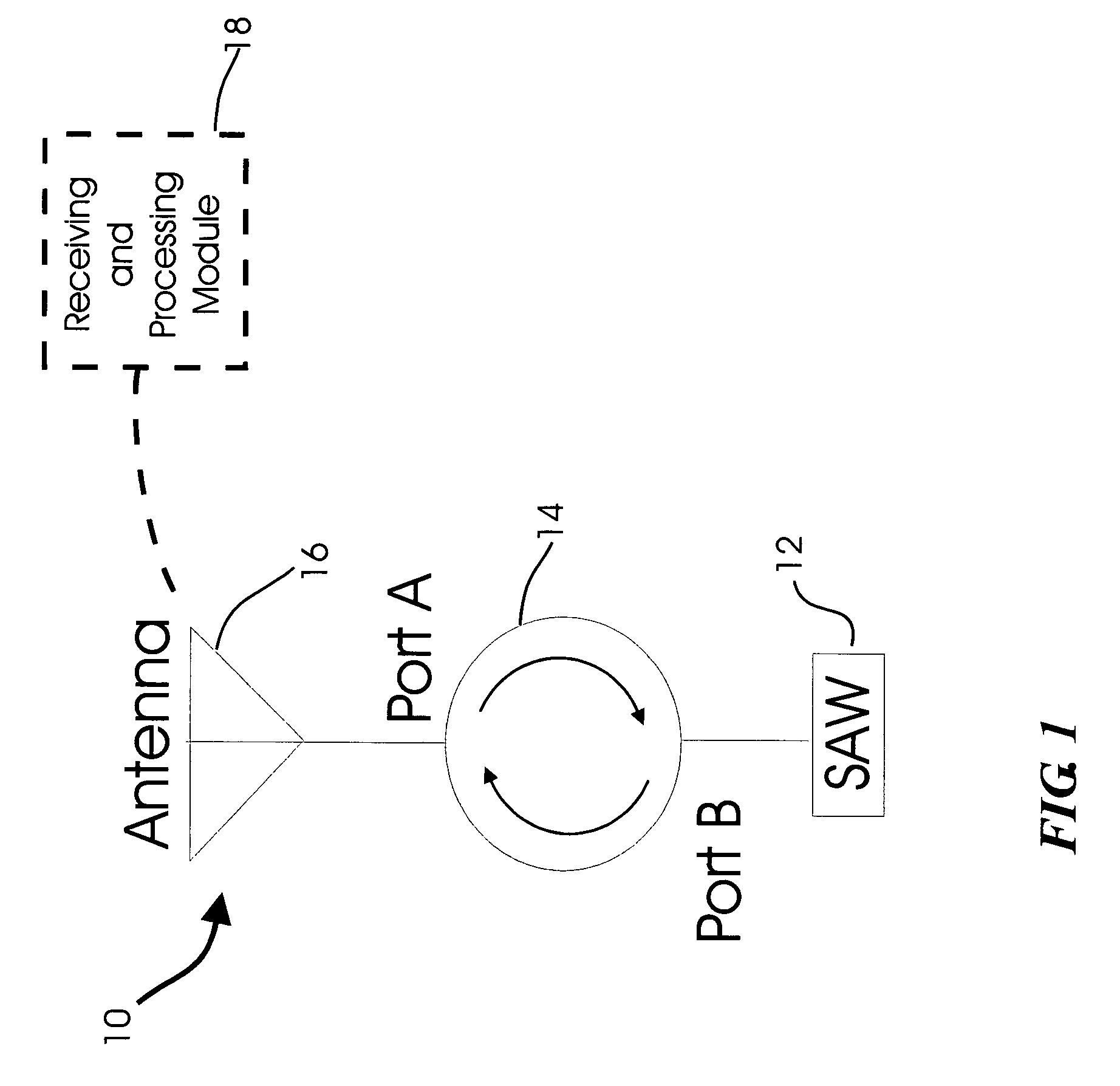
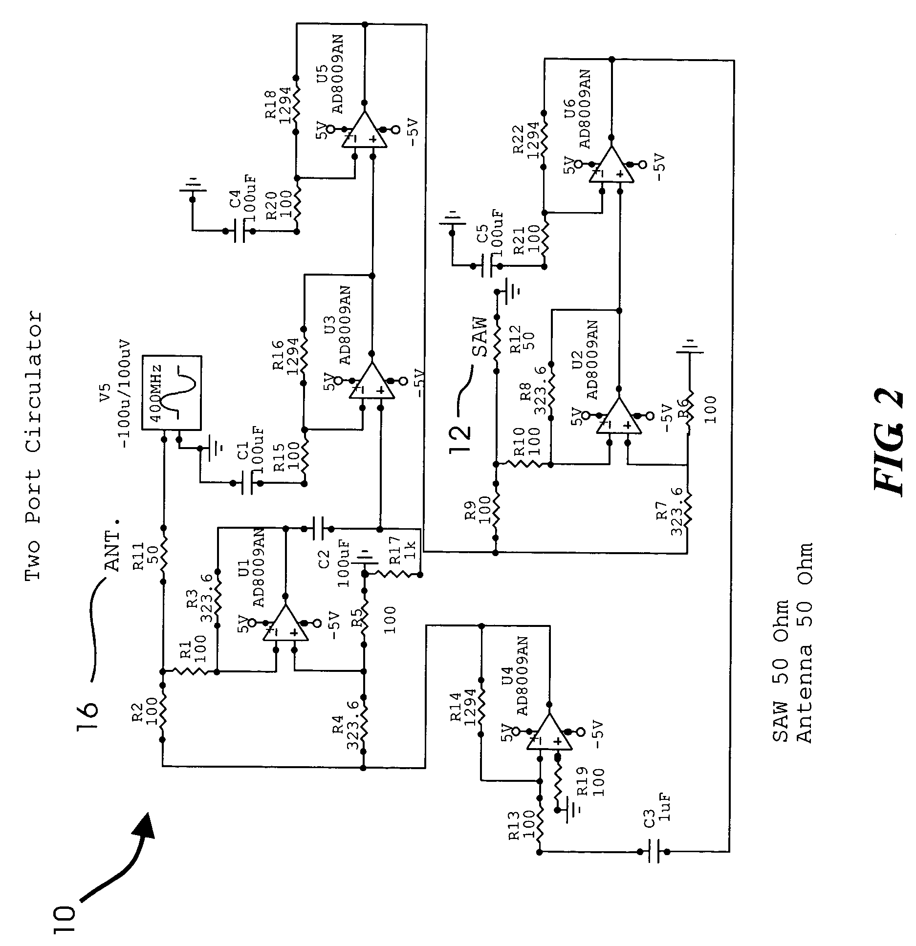
[0096]Referring to the accompanying drawings wherein like reference numerals refer to the same or similar elements, an arrangement for providing a boosted signal from a SAW device is designated generally as 10 and comprises a SAW device 12, a circulator 14 having a first port or input channel designated Port A and a second port or input channel designated Port B, and an antenna 16 (see FIG. 1). The circulator 14 is interposed between the SAW device 12 and the antenna 16 with Port A receiving a signal from the antenna 16 and Port B receiving a signal from the SAW device 12.

[0097]In use, the antenna 16 receives a signal when a measurement from the SAW device 12 is desired and a signal from the antenna 16 is switched into Port A where it is amplified and output to Port B. The amplified signal from Port B is directed to the SAW device 12 for the SAW device 12 to provide a delayed signal indicative of the property or characteristic measured or detected by the SAW devic...


PUM


Abstract

Arrangement for providing a boosted signal from a signal-generating device, such as a SAW device or an RFID tag, including an antenna and a circulator having a first port connected to the antenna to receive a signal therefrom and a second port connectable to the device to provide a signal thereto and receive a signal therefrom. The circulator amplifies the signal from the antenna and the signal received from the device such that a twice-amplified signal is directed to the antenna. A receiving and processing module transmits a signal to the antenna causing the antenna to generate its signal and receive a signal from the antenna derived from the twice-amplified signal. Various pumping systems for vehicle tires and electricity generating systems which generate energy upon rotation of a tire are also disclosed.

Description

CROSS REFERENCE TO RELATED APPLICATION[0001]This application claims priority under 35 U.S.C. §119(e) of U.S. provisional patent application Ser. No. 60 / 415,862 filed Oct. 3, 2002, the entire contents of which are incorporated by reference herein.FIELD OF THE INVENTION[0002]The present invention relates to apparatus and methods for boosting signals to signal-receiving and signal-activated sensors and other devices, and boosting signals from signal-generating sensors and other devices.[0003]More particularly, the present invention relates to apparatus and method for boosting signals to and from surface-acoustic-wave (SAW) devices and passive radio-frequency identification (RFID) tags. The present invention also relates to boosting signals to and / or from radar antennas that backscatter energy based on the resonance.[0004]In general, the signal-boosting apparatus and methods can be used in whatever applications the sensors or radar antennas are used, including but not limited to vehicul...

Claims


Application Information

Patent Timeline
IPC IPC(8): B60C23/00B60C23/04
CPCB60C23/0433G06K7/10178Y10T137/3584Y10T137/36
Inventor BREED, DAVID S.JOHNSON, WENDELL C.DUVALL, WILBUR E.
Owner AMERICAN VEHICULAR SCI
Learn More