
Pump

Active Publication Date: 2009-05-14
XYLEM IP HLDG
View PDF4 Cites 5 Cited by
  • Summary
  • Abstract
  • Description
  • Claims
  • Application Information

AI Technical Summary

Benefits of technology

[0008]The present invention aims at obviating the aforementioned disadvantages of previously known pumps, and at providing an improved pump. A primary object of the present invention is to provide an improved pump of the initially defined type, which in a reliable way admits large sol d matter to pass through the pump, without having to cut up the solid matter into smaller pieces. It is another object of the present invention to provide a pump with respect to the reduce friction between the impeller and the drive shaft in the axial direction, in order to get a better movability or the impeller. It is yet another object of the present invention to provide a pump having an improved durability, thanks to a reduced friction in the interface between the impeller and the drive shaft, and by that a more reliable control of the impeller during movement.
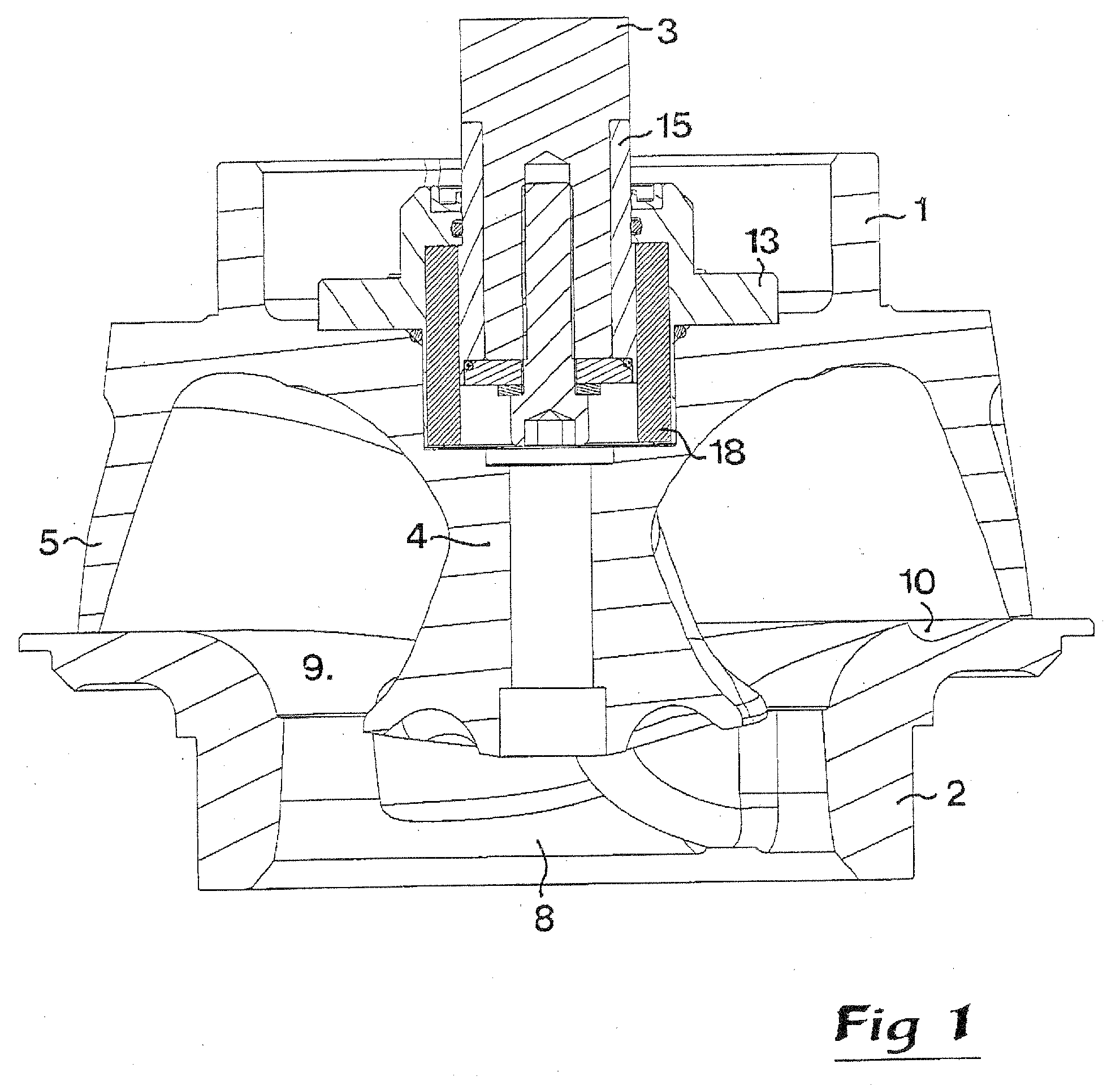
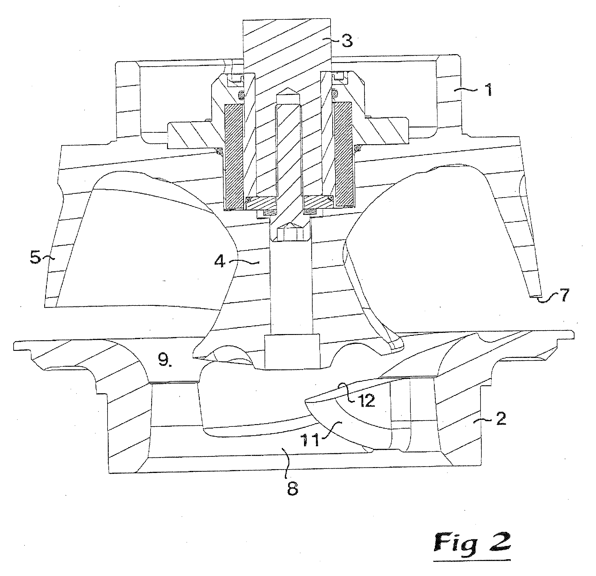
[0012]In a preferred embodiment of the present invention, the groove extends in a spiral shape from a centrally located open channel in the impeller seat to the periphery thereof, along the direction of rotation of the impeller. This means that if the leading edge of the vane of the impeller hit a piece of solid matter, the solid matter will get forced outwards towards the impeller seat as a consequence of the centrifugal force and that the leading edge of the vane is back swept. When the solid matter meets the groove in the top surface of the impeller seat it will follow the shape of the groove outwards and at the same time lift the impeller from the impeller seat, and thus quickly be passed through the pump.

Problems solved by technology

In sewage stations, septic tanks, wells, etc., it often occur that solid matter or pollutants, such as socks, sanitary pads, paper, etc., clogs the submersible pump that is lowered into the basin of the system.
However, the cutting up of the solid matter is energy intensive, which is adverse especially since pumps of this kind usually operates for long periods of time.
One drawback with this type of pump is that the solid matter often get tangled around the leading edge of the vane.
A huge drawback is that the pump has a really low efficiency all the time.
Furthermore, they only admit a small gap between the impeller and the impeller seat.
But the movability is strongly limited and the object solved is only to admit operational start in a dry state, e.g. now liquid in the pump.
More precisely, none of the abovementioned, or other, documents present a solution, or an object, usable for letting through large pieces of solid matter.
Even though small pieces of solid matter might pass through the gap that is formed between the lower edge of the impeller and the impeller seat, it is more likely that large pieces of solid matter will get stuck in the narrow gap formed.
In a worst case scenario, the impeller might get totally jammed and thus seriously damage the pump.
Such an unintentional shutdown is costly, due to expensive, cumbersome and unplanned maintenance work.
If the inlet is blocked the only effect is that less fluid will get pumped through the pump, but if the impeller is jammed he pump might get damaged.
Furthermore, submergible pumps are used to pump fluid from basins that are hard to get access to for maintenance and the pumps often operate for long periods of time, not infrequently up to 12 hours a day or more.

Method used


Image

  • Pump
  • Pump
  • Pump

Examples


Embodiment Construction

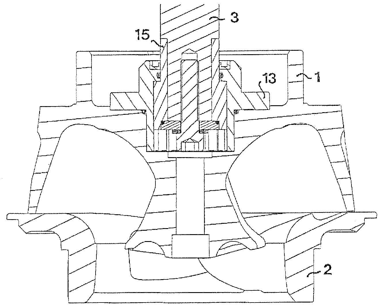
[0023]FIGS. 1 and 2 snow an impeller 1 and an impeller seat 2, usually accommodated in a pump housing of a pump (not shown). The other parts of the pump are removed for the sake of simplicity of reading the figures. The invention relates to pumps in general, but in the preferred embodiment the pump is constituted by a submergible centrifugal pump.

[0024]In a preferred embodiment of the present invention the impeller seat 2 is constituted by an insert releasably connected to the pump housing by being located in a seat in the pump housing in such a way that the insert cannot rotate relative to the pump housing. The impeller 1 is suspended in a drive shaft 3 extending from above, and is rotatable in the pump housing. The first, upper end (not shown) of the drive shaft 3 is connected to the engine of the pump. The second, lower end of the drive shaft 3 is connected to the impeller 1 by means of a joint in such a way that the impeller 1 is movable in the axial direction along the drive sh...


PUM


Abstract

The invention relates to a pump for pumping contaminated liquid including solid matter, comprising a pump housing provided with a rotatable impeller suspended in a drive shaft and having at least one vane, and an impeller seat, at least one part of the impeller and the impeller seat being movable in the axial direction in relation to each other. Furthermore, the impeller seat presents at least one groove in the top surface thereof.

Description

TECHNICAL FIELD OF THE INVENTION[0001]The present invention relates generally to the field of pumps for, sewage or waste water, and more specifically to a pump for pumping unscreened contaminated liquid including solid matter, such as plastic materials, hygiene articles, textile, rags, etc. Said pump comprises a pump housing provided with a rotatable impeller suspended in a drive shaft and having at least one vane, and an impeller seat, at least one part of the impeller and the impeller seat being movable in the axial direction in relation to each other.BACKGROUND OF THE INVENTION[0002]In sewage stations, septic tanks, wells, etc., it often occur that solid matter or pollutants, such as socks, sanitary pads, paper, etc., clogs the submersible pump that is lowered into the basin of the system. The contaminations are sometimes too big to pass through the pump if the impeller and the impeller seat are located at a fixed distance from each other.[0003]In order to get rid of the clogging...

Claims


Application Information

Patent Timeline
IPC IPC(8): F04D29/18
CPCF04D29/2288F04D7/045F04D29/20F04D29/042F04D7/04F04D29/04F04D15/00F04D29/16
Inventor ANDERSSON, PATRIK
Owner XYLEM IP HLDG
Learn More