Turbomolecular vacuum pump with the rotor and stator vanes

a vacuum pump and rotor technology, applied in the direction of liquid fuel engines, marine propulsion, vessel construction, etc., can solve the problems of reducing the efficiency of pump compression and pumping, affecting the pump compression performance, and reducing so as to improve the pumping of lighter gases and reduce the complexity of forevacuum pumps.

Inactive Publication Date: 2005-06-28
LEYBOLD HERAEUS GMBH & CO KG
View PDF9 Cites 4 Cited by
  • Summary
  • Abstract
  • Description
  • Claims
  • Application Information

AI Technical Summary

Benefits of technology

[0009]The application improves the pumping of lighter gases. Moreover, the benefit is obtained impairing the compression and pumping performance of the pump (compression, pumping capacity, throughput) for gases having a higher molar mass. Finally, blades and the vanes designed in accordance with the present invention maintain their improved pumping properties far into the Knudsen range, so that the forevacuum tolerance of a turbomolecular pump equipped with such blades or vanes is, compared to the state-of-the-art, far more favorable. The complexity for the forevacuum pumps can be reduced significantly.

Problems solved by technology

Moreover, the benefit is obtained impairing the compression and pumping performance of the pump (compression, pumping capacity, throughput) for gases having a higher molar mass.

Method used


Image

  • Turbomolecular vacuum pump with the rotor and stator vanes
  • Turbomolecular vacuum pump with the rotor and stator vanes
  • Turbomolecular vacuum pump with the rotor and stator vanes

Examples


Embodiment Construction

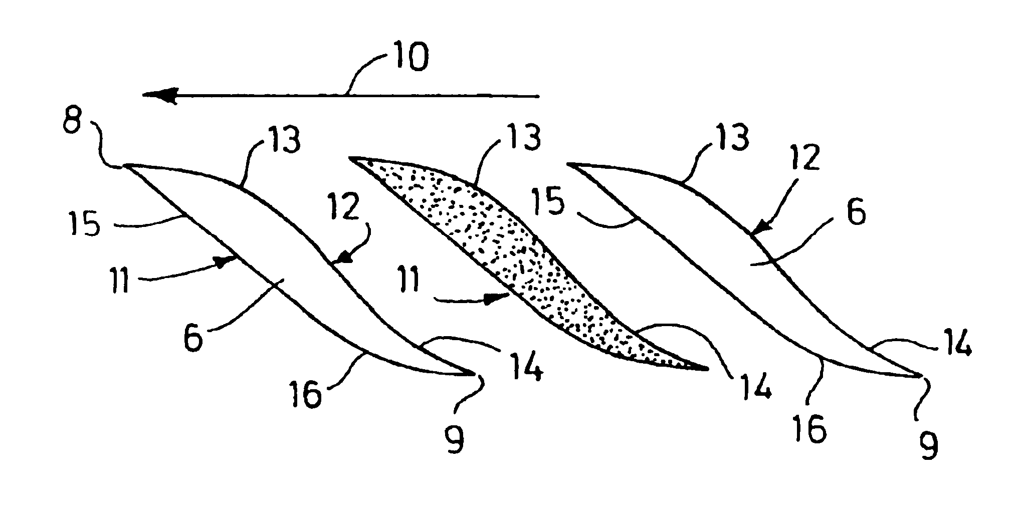
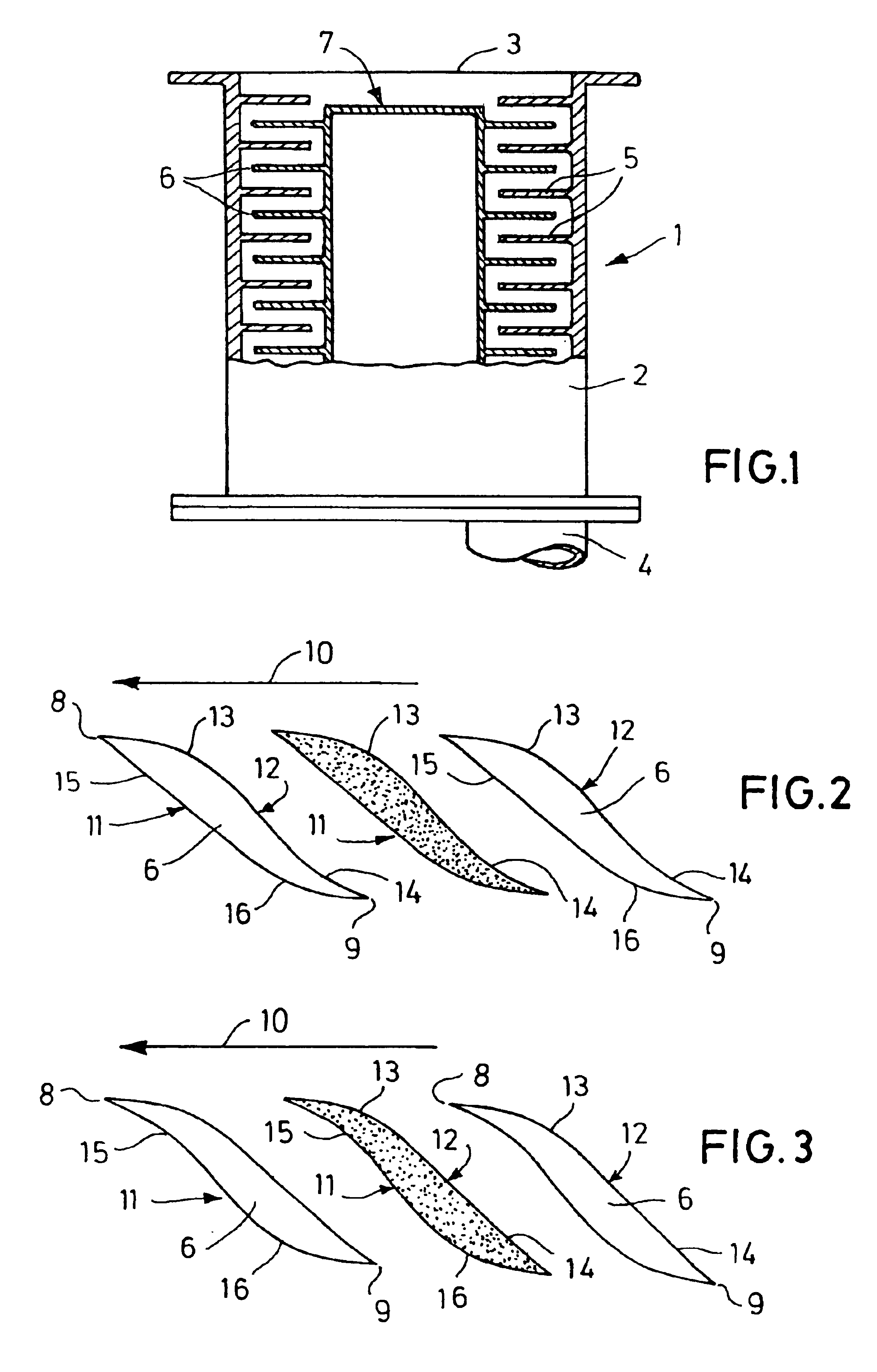
[0014]The turbomolecular vacuum pump 1 depicted in FIG. 1 comprises a housing / stator 2, an inlet 3, an outlet 4, stator vanes 5 and rotor blades 6. In a known manner not specifically detailed, the stator vanes 5 are components of rows of stator vanes which are joined to the housing / stator 2. The rotor blades 6 are components of rows of rotor blades which are affixed at rotating body 7, for example a shaft, or which are designed as a single piece with said rotating body. The rows of rotor blades and stator vanes engage alternately with opposing angles of attack and effect pumping of the gases from the inlet 3 to the outlet 4.

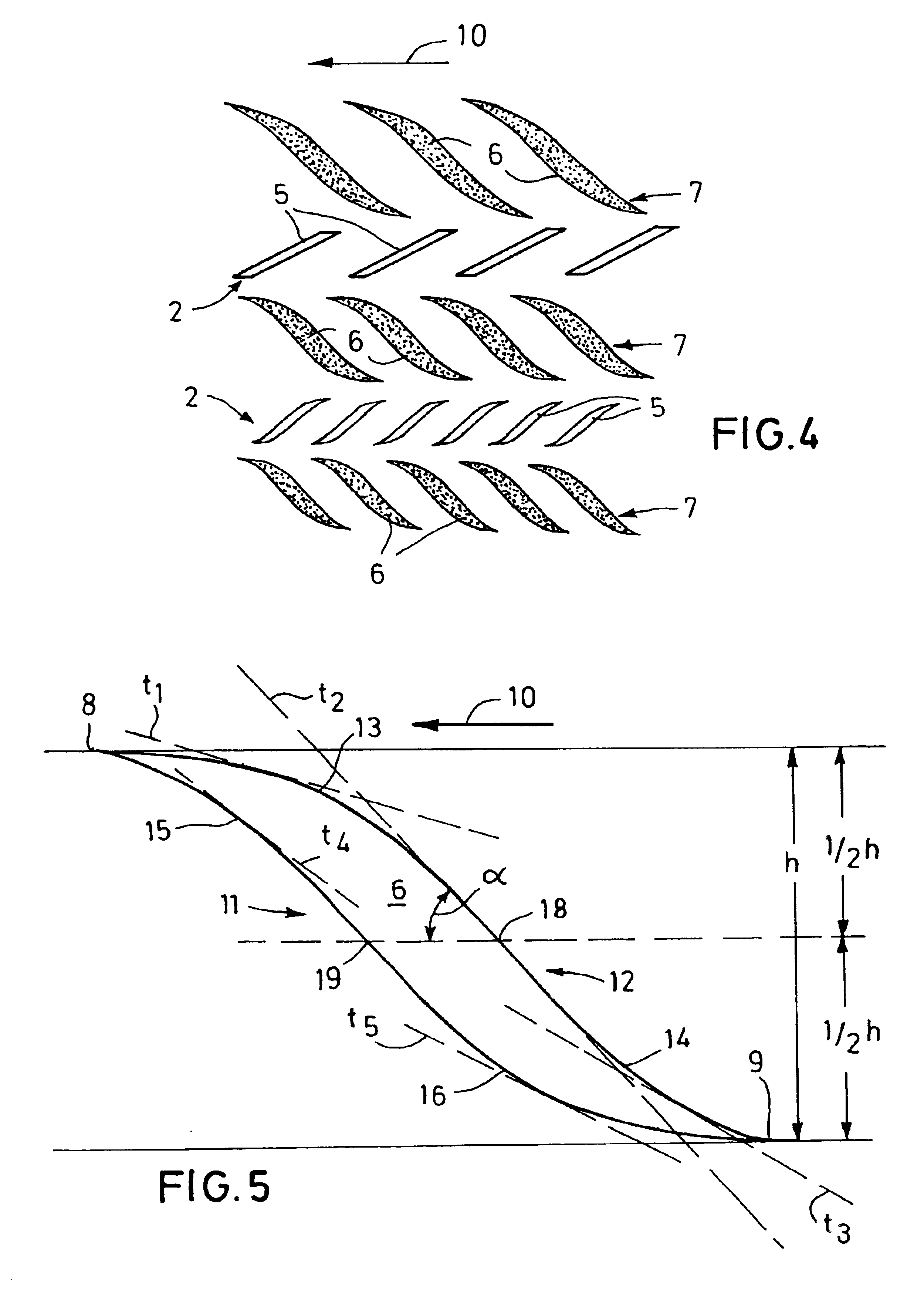
[0015]Depicted in FIGS. 2 to 5 are various embodiments of blades / vanes designed in accordance with the present invention (developed view). The upper edge 8 depicted in the Figures faces, in each instance, the suction side of the pump 1, and the bottom edge 9 in each instance faces in the delivery side. Depicted are, in each instance, sections through the blades / v...


PUM


Abstract

A turbomolecular vacuum pump (1) has an inlet (3) and an outlet (4) and rotor and stator vanes (5 and 6), situated between the inlet and outlet. The rotor vanes (6) have front sides (11) and rear sides (12) in relation to the direction of rotation. At least a part of the rotor vanes (6) have a rear side (12) which is convex on the suction-side and concave on the delivery side. Alternately, at least part of the rotor vanes (6) have a front side (11), which is concave on the suction side and convex on the delivery side.

Description

BACKGROUND OF THE INVENTION[0001]The present invention relates to turbomolecular vacuum pumps.[0002]Turbomolecular vacuum pumps are designed similar to turbines, with stator vanes and rotor blades. A significant pumping action is only obtained in the range of molecular flow (p<10−3 mbar). In the Knudsen flow range which then follows, pumping performance is reduced more and more at increasing pressure.[0003]The pumping principle of a turbomolecular vacuum pump is based on the effect that the gas molecules which are to be pumped, obtain an impulse in the direction of the pumping action by impact with the rotor blades and stator vanes. This effect is only obtained when the circumferential velocities of the rotor blades are in the order of magnitude of the mean thermal velocity of the gas molecules to be pumped.[0004]The mean thermal velocity of gas molecules is dependent on their molar mass. For H2 (mass 2) it amounts to approximately 1760 m / s and for nitrogen (mass 28) to approxima...

Claims


Application Information

Patent Timeline
Patent Type & Authority Patents(United States)
IPC IPC(8): F04D19/00F04D19/04F04D29/38
CPCF04D29/384F04D19/042F04D29/324F05D2250/70
Inventor BEYER, CHRISTIANENGLANDER, HEINZKLINGNER, PETERLAERBUSCH, MARTIN
Owner LEYBOLD HERAEUS GMBH & CO KG
Why Eureka
Try Eureka