
Pump for pumping contaminated liquid including solid matter

a technology for contaminated liquid and pumps, applied in the direction of engines, liquid fuel engines, rotors, etc., can solve the problems of increasing the risk of damage to the seal, clogging the submersible pump, and reducing the volume of the cavity defined by the seal housing cover and the impeller, so as to achieve the effect of increasing the ability to pass solid matter through the pump

Inactive Publication Date: 2009-01-22
XYLEM IP HLDG
View PDF5 Cites 8 Cited by
  • Summary
  • Abstract
  • Description
  • Claims
  • Application Information

AI Technical Summary

Benefits of technology

[0008]The present invention aims at obviating the aforementioned disadvantages of previously known pumps, and at providing an improved pump. An object of the present invention is to provide a pump of the initially defined type, in which the pressure against the seal located between the seal housing cover and the drive shaft is adapted in order not to damage said seal during operation. It is another object of the present invention to provide a pump, in which the inertial force against axial movement of the impeller is reduced. It is yet another object of the present invention to provide a pump having an improved durability, especially concerning the durability of the seal.
[0013]According to a preferred embodiment, the impeller may be moved a great distance from the impeller seat in the axial direction, preferably as much as the diameter of the open channel of the impeller seat. Then the ability to pass solid matter through the pump is considerably increased.

Problems solved by technology

In sewage stations, septic tanks, wells, etc., it often occur that solid matter or pollutants, such as socks, sanitary pads, paper, etc., clogs the submersible pump that is lowered into the basin of the system.
A decisive problem arises in the case when the impeller is movable in relation to the seal housing cover, and accordingly the volume of the cavity defined by the seal housing cover and the impeller is changed, i.e. decreased or increased.
Thereby a great pressure peak arises in the cavity and the risk of damaging the seal is increased.
If said seal is damaged the engine and the entire pump may be damaged, and such an unintentional shutdown is costly, due to expensive, cumbersome and unplanned maintenance work.
Furthermore, submergible pumps are used to pump fluid from basins that are hard to get access to for maintenance and the pumps often operate for long periods of time, not infrequently up to 12 hours a day or more.

Method used


Image

  • Pump for pumping contaminated liquid including solid matter
  • Pump for pumping contaminated liquid including solid matter
  • Pump for pumping contaminated liquid including solid matter

Examples


Embodiment Construction

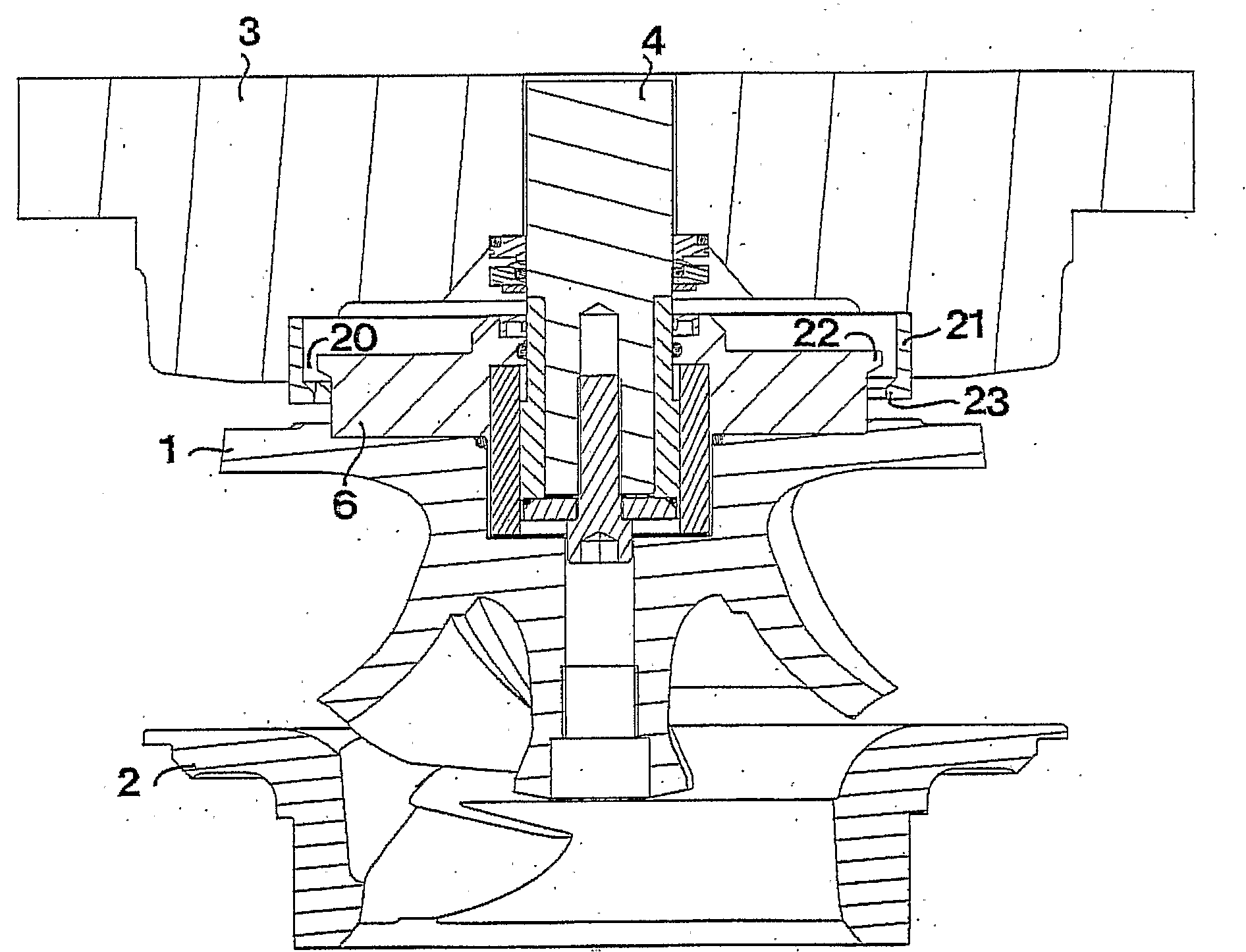
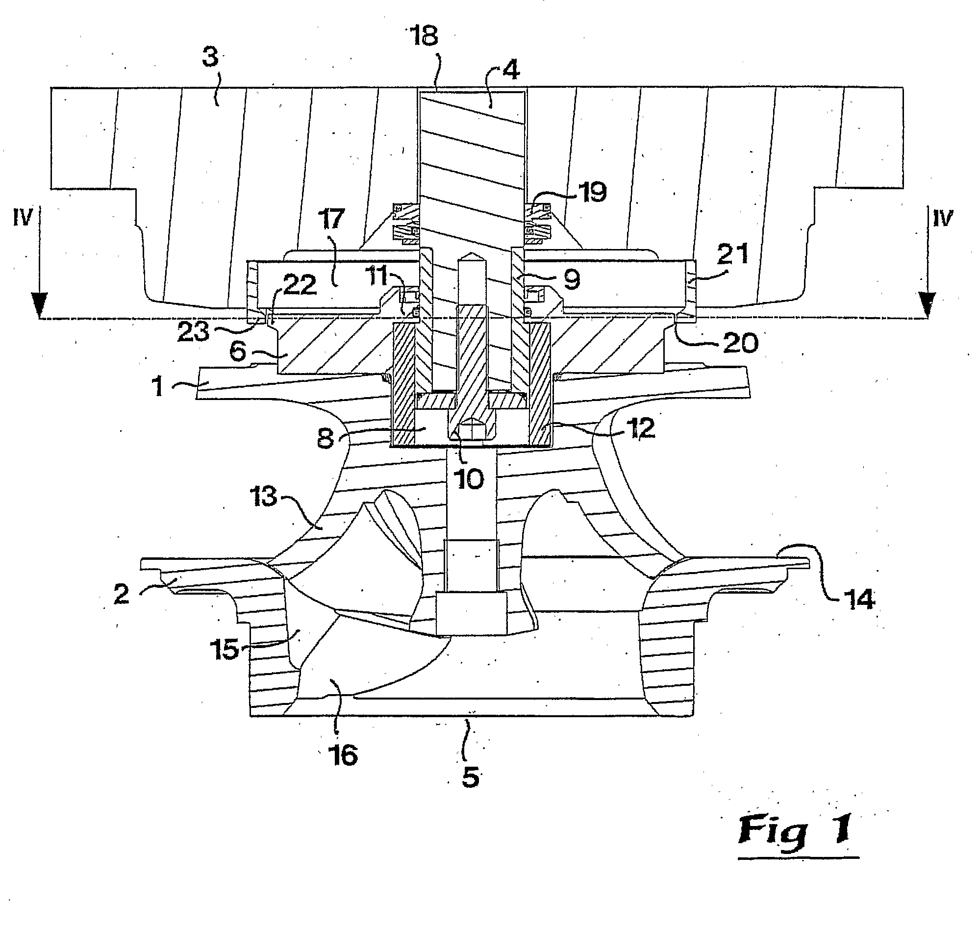
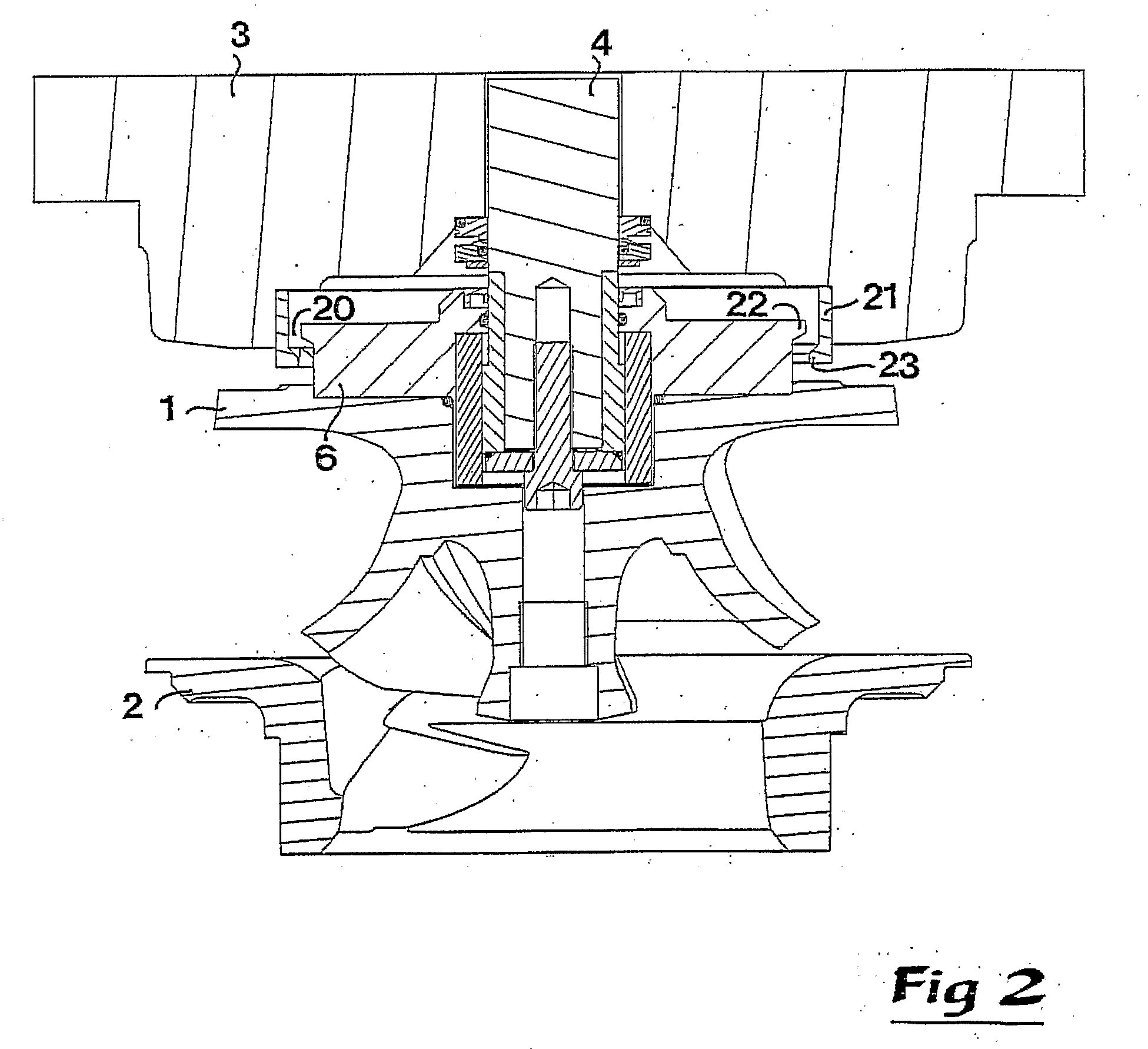
[0019]FIGS. 1-3 shows an impeller 1, an impeller seat 2 accommodated in a pump housing of a pump, and a seal housing cover 3. The other parts of the pump / pump housing are removed for the sake of simplicity of reading the figures. The invention relates to pumps in general, but in the preferred embodiment the pump is constituted by a submergible centrifugal pump.

[0020]In a preferred embodiment of the present invention the impeller seat 2 is constituted by an insert releasably connected to the pump housing by being located in a seat (not shown) in the pump housing in such a way that the insert cannot rotate relative to the pump housing. The impeller 1 is suspended in a drive shaft 4 extending from above, and is rotatably journalled in the pump. More precisely, the impeller 1 is rotatable in a pump chamber of the pump. An upper end (not shown) of the drive shaft 4 is connected to an engine (not shown) of the pump. In this connection it shall be pointed out that the drive shaft 4 is cut ...


PUM


Abstract

The invention relates to a pump for pumping contaminated liquid including solid matter, comprising an impeller (1), which is rotatable in a pump chamber of said pump, the impeller (1) being movable in the axial direction in relation to a seal housing cover (3) between a first position adjacent to an impeller seat (2) and a second position spaced apart from said impeller seat (2), said pump also comprising a cavity (17) defined by the seal housing cover (3) and the impeller (1), and at least one opening gap (20) connecting said cavity and said pump chamber. Furthermore, said opening gap (20) has a first flow area when the impeller (1) is in the first position, and a second flow area bigger than said first flow area when the impeller (1) is' spaced apart from said first position.

Description

TECHNICAL FIELD OF THE INVENTION[0001]The present invention relates generally to the field of pumps for sewage or waste water, and more specifically to a pump for pumping unscreened contaminated liquid including solid matter, such as plastic materials, hygiene articles, textile, rags, etc. Said pump comprises an impeller, which is rotatable in a pump chamber of said pump, the impeller being movable in the axial direction in relation to a seal housing cover between a first position adjacent to an impeller seat and a second position spaced apart from said impeller seat, said pump also comprising a cavity defined by the seal housing cover and the impeller, and at least one opening gap connecting said cavity and said pump chamber.BACKGROUND OF THE INVENTION[0002]In sewage stations, septic tanks, wells, etc., it often occur that solid matter or pollutants, such as socks, sanitary pads, paper, etc., clogs the submersible pump that is lowered into the basin of the system. The contamination...

Claims


Application Information

Patent Timeline
Patent Type & Authority Applications(United States)
IPC IPC(8): F04D29/08
CPCF04D15/0033F04D7/04F04D29/04F04D7/045
Inventor ANDERSSON, PATRIK
Owner XYLEM IP HLDG
Learn More