Electric motor, power apparatus using the same, and self-propelled snow remover

a technology of electric motors and power equipment, applied in the direction of electric energy management, electric devices, driver interactions, etc., can solve the problems of increasing the number of manufacturing steps, increasing the heat generated by resistors, and complicated configuration of inner rotors and outer stators, so as to reduce torque ripple and simple configuration

Active Publication Date: 2008-11-27
HONDA MOTOR CO LTD
View PDF14 Cites 17 Cited by
  • Summary
  • Abstract
  • Description
  • Claims
  • Application Information

AI Technical Summary

Benefits of technology

[0020]It is a first object of the present invention to reduce torque ripple using a simple configuration.
[0021]A second object of the present invention is to ensure a smaller power apparatus and energy savings, and to prevent overcharging of a battery during regenerative braking.
[0022]A third object of the present invention is to reduce the power consumption of a traveling electric motor in a self-propelled snow remover.

Problems solved by technology

Also, the configuration of the inner rotor and the outer stator is made more complicated and the number of manufacturing steps is increased by the presence of the skew.
However, a bypass circuit resistor and a regenerative resistor for sending very large regenerative current are required in the device.
Furthermore, when the amount of heat generated by the resistors is considerable, an air cooling fan or another heat dissipating device must be provided.
Since this leads to a more complicated structure, there is room for improvement.
A driver circuit having a large electric current supply capability is large in size and produces a considerable amount of heat.
Therefore, there is a limit to reducing the size of the power apparatus.
Also, since the amount of snow removed by the auger is increased when the travel speed is increased, the crawlers are subjected to a greater load.
Also, since snow removal is not performed, the load on the crawlers is low.
Therefore, power consumption is inevitably high in relative terms even when the snow remover is merely being moved.
However, driving the engine in order to merely move the snow remover is a wasteful operation.

Method used


Image

  • Electric motor, power apparatus using the same, and self-propelled snow remover
  • Electric motor, power apparatus using the same, and self-propelled snow remover
  • Electric motor, power apparatus using the same, and self-propelled snow remover

Examples


first embodiment

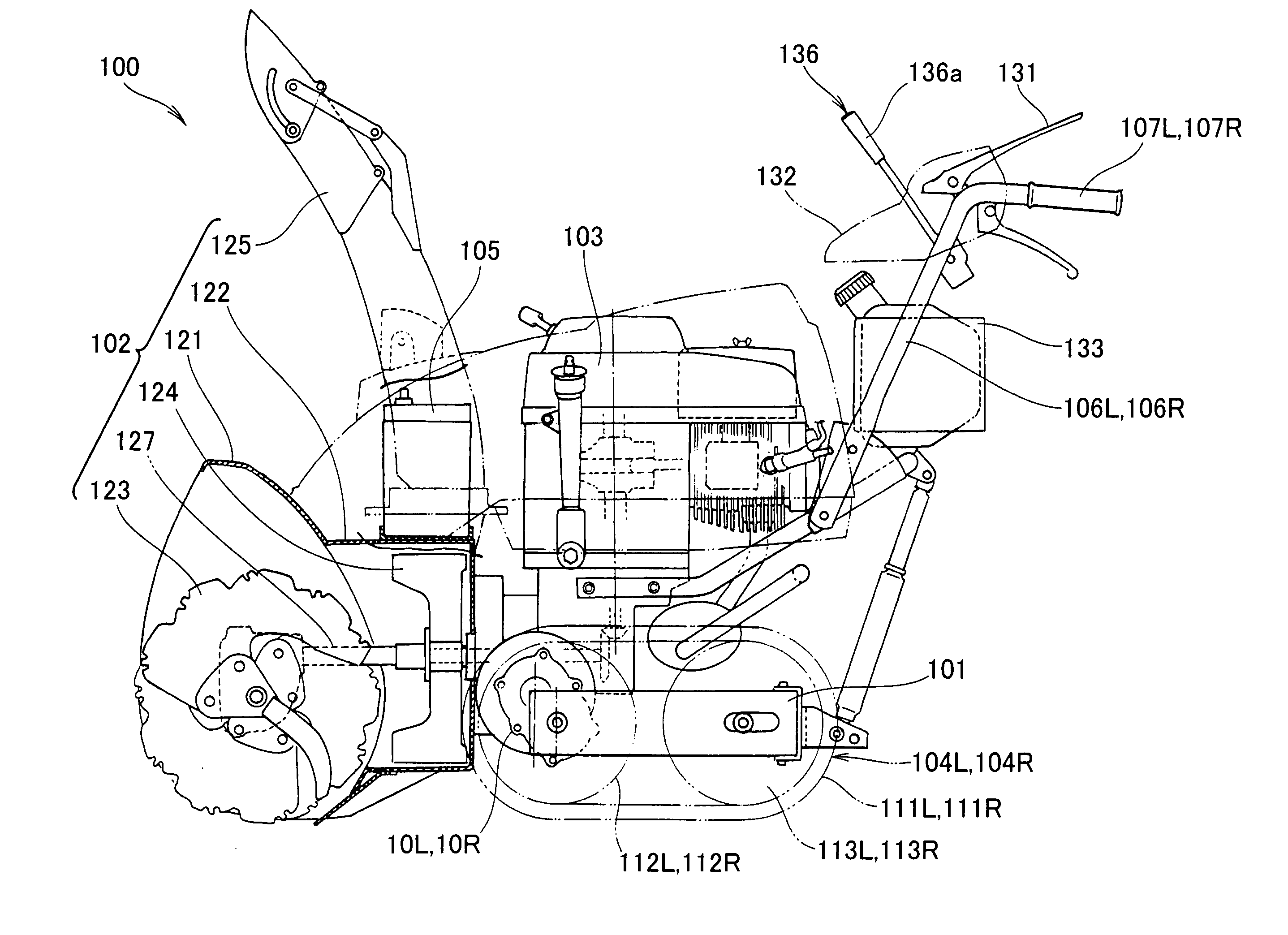
[0180]FIG. 13 is a control flowchart (first embodiment) of the controller shown according to the present invention.

[0181]ST01: The drive current Imr supplied from the driver circuit 143L to the electric motor 10L is detected by the electric current sensor 145L

[0182]ST02: A determination is made whether the driver current Imr is less than a predetermined reference current Ims set in advance. If YES, the process proceeds to ST03, and if NO, the process proceeds to ST04. At this point, the reference current Ims is the required drive current supplied when the self-propelled snow remover 100 is made to travel without removing snow by the snow removing implement 102.

[0183]ST03: Since the determination is YES, a light-load control mode is selected from among a plurality of control modes stored in the controller 133. The light-load control mode is a control mode for controlling the driver circuit 143L so as to supply drive current only to a predetermined winding 38 in the windings 38. For e...

second embodiment

[0193]FIG. 14 is a control flowchart (second embodiment) of the controller according to the present invention.

[0194]ST11: Various signals are read.

[0195]ST12: It is determined whether the snow removal operation is stopped. If YES, the process proceeds to ST13, and if NO, the process proceeds to ST15. For example, it is determined that the snow removal operation is stopped when the auger switch 135 is off.

[0196]ST13: A determination is made whether the vehicle is traveling. If YES, the process proceeds to ST14, and if NO, control in the control flow is ended. For example, it is determined that the vehicle is set in motion when the operating lever 136a has been swung forward or rearward (when tilted).

[0197]ST14: A light-load control mode is selected from among a plurality of control modes stored in the controller 133. The light-load control mode is a control mode for controlling the driver circuit 143L so as to supply drive current only to a predetermined winding 38 in the windings 38...


PUM


Abstract

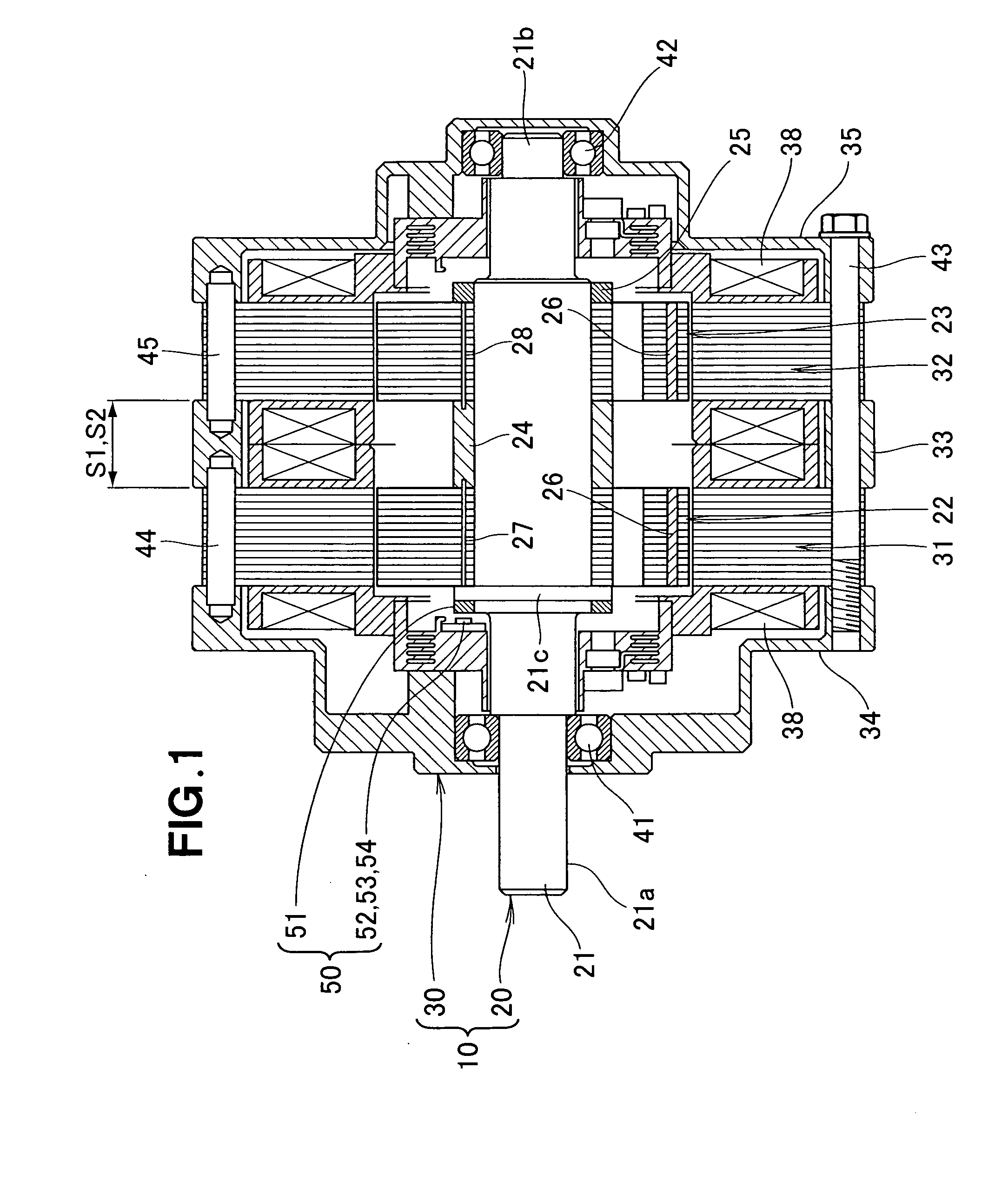
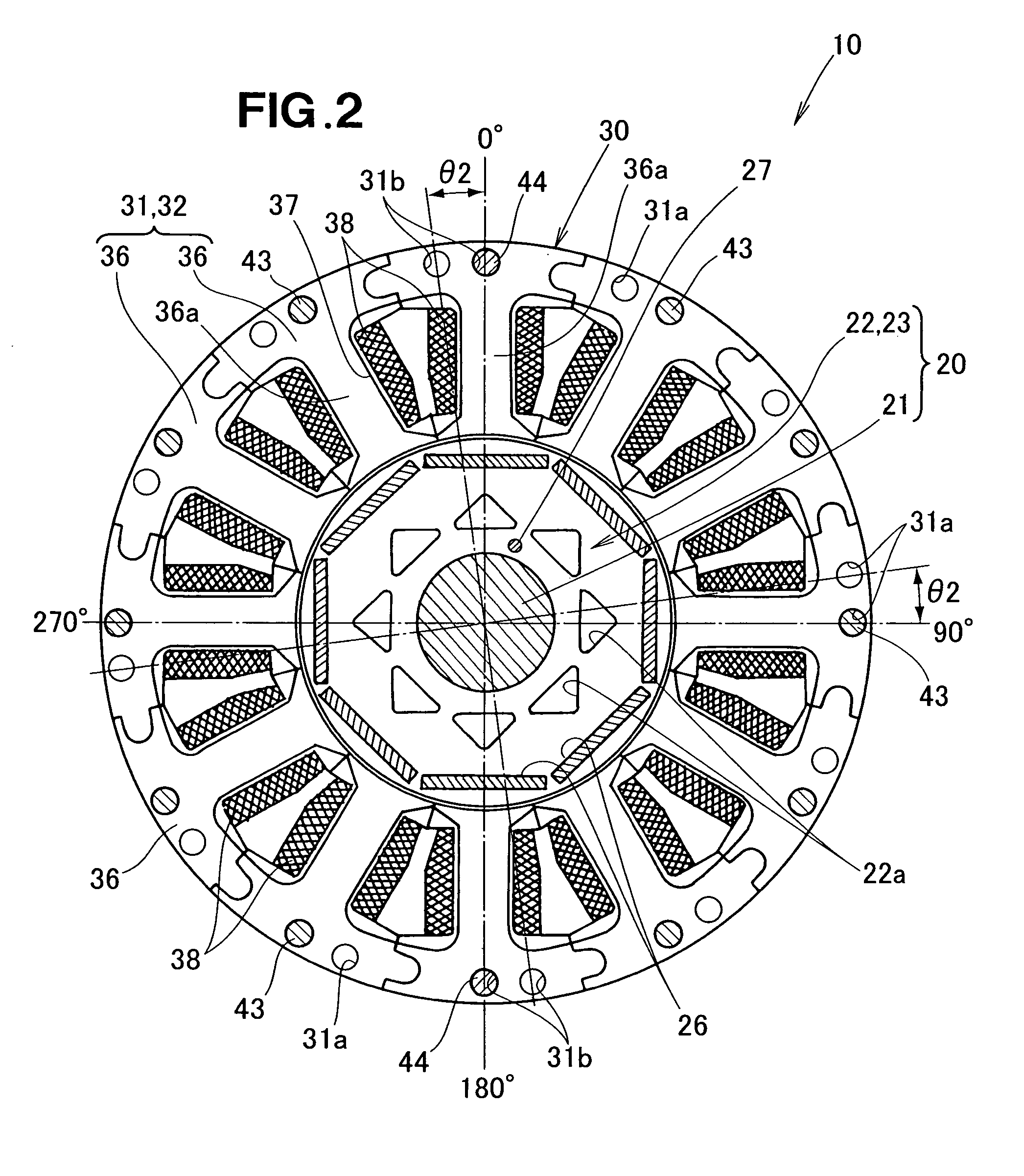
A electric motor is disclosed in which torque ripple is reduced. The electric motor includes a single motor shaft. Rotors are disposed so as to be mutually offset in phase, and the rotors are secured to the motor shaft. Stators are arranged so as to individually correspond to the rotors, and the stators are disposed so as to be matched in phase. The phases of torque ripple generated in each motor unit, which is comprised of a combination of a single rotor and a single stator, are offset.

Description

FIELD OF THE INVENTION[0001]The present invention relates to an electric motor having a plurality of rotors arranged axially of a motor shaft thereof, to a power apparatus and to a self-propelled snow remover.BACKGROUND OF THE INVENTION[0002]Methods are currently known in which a plurality of rotors are arranged in an axial direction of a motor shaft in an electric motor, an example of which is disclosed in Japanese Patent Application Laid-Open Publication No. 2006-14477 (JP 2006-14477 A). The conventional electric motor disclosed in JP 2006-14477 A is provided with two motor units accommodated in a single housing.[0003]Each motor unit is comprised of a motor shaft, an inner rotor provided to the motor shaft, and a cylindrical outer stator disposed so as to surround the inner rotor. The motor shafts of the motor units are concentrically disposed and rotate in a mutually independent manner.[0004]The motor shaft of one of the motor units extends outward from one end of the housing. Th...

Claims


Application Information

Patent Timeline
Patent Type & Authority Applications(United States)
IPC IPC(8): E01H5/00H02K16/00H02P3/14H02P31/00
CPCE01H5/04B60L2220/50H02K16/00H02K29/03H02K2201/06H02P6/10B60L2200/40B60L1/003B60L3/003B60L3/0046B60L3/0061B60L3/0084B60L7/14B60L11/1803B60L11/1861B60L15/2009B60L2220/16B60L2220/44B60L2240/36B60L2240/421B60L2240/423B60L2240/427B60L2240/429B60L2240/547B60L2240/549B60L2250/24B60L2260/28B60L2270/145H02K1/148Y02T10/72B60L50/51B60L58/15Y02T10/64Y02T10/70B60L58/12B60L2220/40
Inventor YAMAGISHI, YOSHIHIKOHIROSE, YOSHIHISAMIZOROKE, TSUTOMU
Owner HONDA MOTOR CO LTD
Why Eureka
Try Eureka