Six-phase flux switching type permanent magnet motor

A magnetic flux switching motor and flux switching technology, applied in the directions of magnetic circuit static parts, magnetic circuit rotating parts, magnetic circuit shape/style/structure, etc., can solve the problem of increasing the difficulty and reliability of power converter design, increasing Difficulty in designing coils for each phase winding, increasing design requirements and costs, etc., to achieve the effect of improving low-speed running performance, small positioning torque, and strong fault tolerance.

Inactive Publication Date: 2013-08-14
SOUTHEAST UNIV
View PDF4 Cites 27 Cited by
  • Summary
  • Abstract
  • Description
  • Claims
  • Application Information

AI Technical Summary

Problems solved by technology

[0005] (1) In high-power applications, the three-phase structure leads to a high power level for each phase of the armature winding, which increases the difficulty of designing the coils of each phase winding. Higher requirements increase the design requirements and cost of the entire system;
[0006] (2) In high-power applications, each phase winding will be allocated a large power. In the power conversion system corresponding to the three-phase motor, power devices with large current levels must be selected, or small current power devices must be connected in p

Method used


Image

  • Six-phase flux switching type permanent magnet motor
  • Six-phase flux switching type permanent magnet motor
  • Six-phase flux switching type permanent magnet motor

Examples


Embodiment Construction

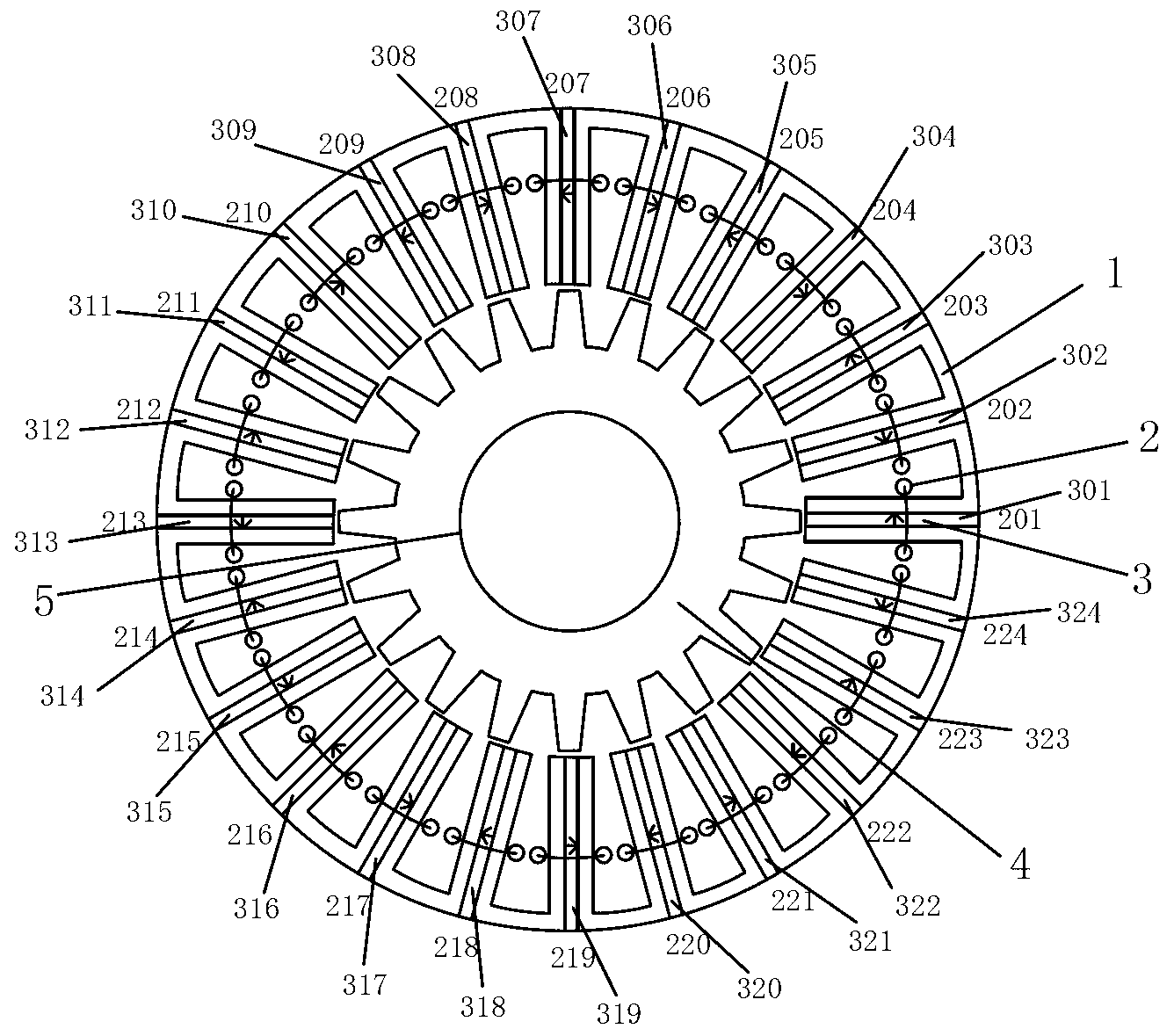
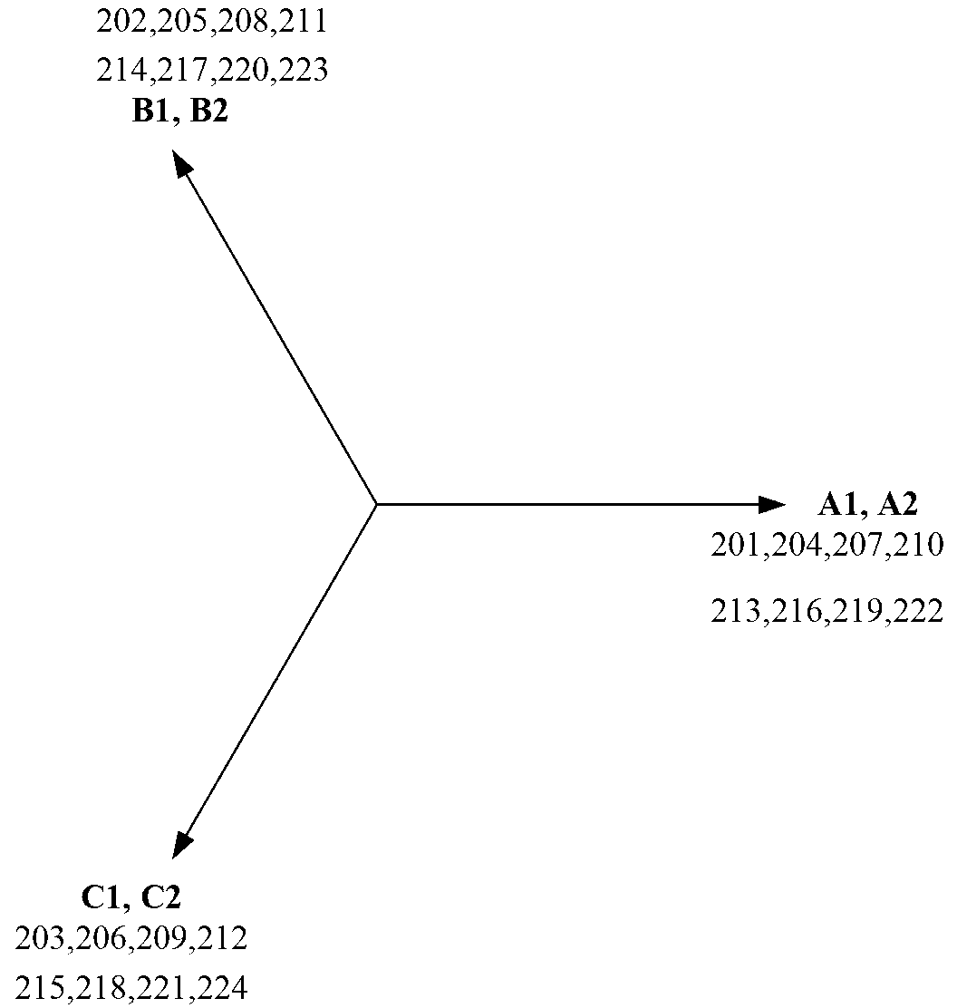
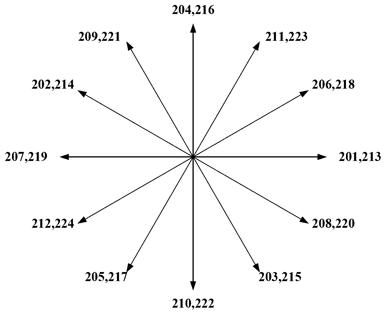
[0037] Taking a six-phase stator with 24 slots / rotor with 20 poles pure permanent magnet structure flux switching motor as an example, such as figure 1 As shown, the permanent magnet flux switching motor of the present invention includes a stator 1 , a concentrated armature winding 2 , a permanent magnet 3 , a rotor 4 and a rotating shaft 5 . Among them, the rotor 4 is located inside the stator 1 (it can also be made into an outer rotor structure), the stator 1 and the rotor 4 are both salient pole structures, and the stator part is composed of 24 "U" shaped stator cores and 24 alternating tangential charging poles. The magnetic permanent magnet and the six-phase symmetrical concentrated armature winding 2 are composed. The six-phase concentrated armature winding 2 includes a first concentrated armature coil 201, a second concentrated armature coil 202, a third concentrated armature coil 203, a fourth concentrated armature coil 204, a fifth concentrated armature coil 205, a ...


PUM


Abstract

The invention provides a six-phase flux switching type permanent magnet motor which comprises stators, rotors and a rotating shaft, wherein each stator adopts a permanent magnet double salient structure, that is, the permanent magnet, the stator core and the armature winding are arranged on each stator, the stator core is assembled by an U-magnetic core and each permanent magnet embedded in the magnetic core, and the permanent magnets are of tangential alternate magnetization; the armature winding is of six-phase armature winding arranged on the stator, the six-phase armature winding adopts centralization coils, and the rotors are made of permeability magnetic material; the magnetizing directions of the permanent magnets are of the tangential of the stator circle, and the magnetizing directions of two adjacent permanent magnets are opposite to each other; the number of the armature coil and the stator groove is even number times of the phase number; and each phase 2n coils winding, and n coils are distributed at the two ends of the diameter of the stator circle respectively. And two three-phrase winding can conduct independent power supplying and generating.

Description

technical field [0001] The invention relates to multi-phase power generation or electromotive technology, in particular to a six-phase magnetic flux switching permanent magnet motor. Background technique [0002] Permanent magnet motors use permanent magnets to generate magnetic fields. Due to the inherent characteristics of permanent magnets, after pre-magnetization, a magnetic field can be established in the surrounding space without additional energy. Compared with the traditional electric excitation motor, this can simplify the motor structure, save the collector ring and brush that are prone to problems, and improve the reliability of the motor operation; it does not require excitation current, that is, there is no excitation loss, which improves the efficiency of the motor. Efficiency and power density of the motor. The flux switching permanent magnet motor adopts the stator permanent magnet structure, the permanent magnet and the armature winding are placed in the st...

Claims


Application Information

Patent Timeline
IPC IPC(8): H02K3/28H02K1/16H02K1/14H02K1/17H02K1/24
Inventor 花为彭锋程明
Owner SOUTHEAST UNIV
Why Eureka
Try Eureka