Built-in permanent magnet motor rotor magnetic field improved design method suitable for industrialization

A permanent magnet motor and rotor magnetic field technology, which is applied in the manufacture of motor generators, stator/rotor bodies, magnetic circuits, etc., can solve the problems of difficult manufacturing of rotor stamping dies, high processing accuracy and high production costs, and reduce positioning torque , Simplify the manufacturing process and reduce the effect of cogging torque

Inactive Publication Date: 2020-08-11
HARBIN INST OF TECH
View PDF6 Cites 1 Cited by
  • Summary
  • Abstract
  • Description
  • Claims
  • Application Information

AI Technical Summary

Problems solved by technology

For multi-pole motors, the arc-shaped surface of the salient-pole rotor has multiple centers, and the die manufacturing of the rotor punch is very difficult, and the machining accuracy and production cost are high.
[0004] Therefore, there is no rotor stamping shape optimization technology suitable for built-in permanent magnet motors in the prior art that meets the requirements of simple process and easy industrialization

Method used


Image

  • Built-in permanent magnet motor rotor magnetic field improved design method suitable for industrialization
  • Built-in permanent magnet motor rotor magnetic field improved design method suitable for industrialization
  • Built-in permanent magnet motor rotor magnetic field improved design method suitable for industrialization

Examples


Embodiment

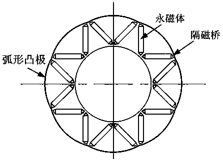
[0033] Such as image 3 As shown, the built-in permanent magnet motor designed in this embodiment has a stator outer diameter of 190 mm, a rotor outer diameter of 110 mm, an axial length of 100 mm, and an air gap length of 2 mm. The rotor has 8 magnetic poles and is designed with 2-section V-shaped magnetic steel.

[0034] When the rotor is designed with a cylindrical punch, the air gap magnetic density amplitude is 0.69 T, ​​the waveform is flat-top wave, the fundamental wave amplitude is 0.85 T, the phase potential amplitude is 97.5 V, and the positioning torque is 102 mNm.

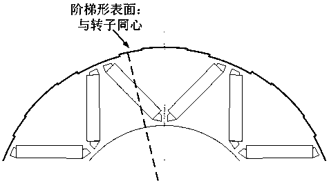
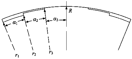
[0035] When the rotor adopts a three-stage stepped arc-shaped punch design, the air gap magnetic density amplitude is 0.73 T, the waveform is an approximate sine wave, and the fundamental wave amplitude is 0.84 T. The phase potential amplitude is 110.5 V, which is 13.3% higher than that of the cylindrical punch. The positioning torque is 14.2 mNm, which is 86.1% lower than the cylindrical punching. The cal...


PUM


Abstract

The invention discloses a built-in permanent magnet motor rotor magnetic field improved design method suitable for industrialization, and the method comprises the following steps: 1, taking one magnetic pole of a rotor as a unit, and determining the number of steps of a stepped concentric arc and the radius of each stepped concentric arc step according to the size of the outer circle of the rotorand the number of the magnetic poles of the rotor; 2, sequentially repeating the step-shaped concentric arc shape determined in the step 1 according to the number of rotor magnetic poles, and salientpole surfaces under all rotor poles are formed; and 3, carrying out sectional processing on the shape of the outer surface of the rotor under each magnetic pole. On the premise of ensuring the outputtorque, the cogging torque of the built-in permanent magnet motor can be effectively reduced, and the industrial technology development of the built-in permanent magnet motor is promoted.

Description

Technical field [0001] The invention relates to a method for designing a rotor magnetic field of a built-in permanent magnet motor, in particular to a method for designing a salient pole rotor punching piece structure that meets the requirements of mass production, has simple process and structure, and is convenient to manufacture. Background technique [0002] Built-in permanent magnet motors, compared with surface-mounted permanent magnet motors, have the advantages of solid structure, easy processing, and strong magnetic weakening ability. They have been widely used in new energy vehicles, vacuum cleaners and other fields. However, the built-in permanent magnet makes the inductance of the rotor's quad-direction axis unequal. The resulting salient pole effect will affect the sine of the air gap magnetic field, produce a larger cogging torque, reduce the stability of the motor output torque, and it is also very detrimental to the vibration and noise reduction of the system. In ...

Claims


Application Information

Patent Timeline
Patent Type & Authority Applications(China)
IPC IPC(8): H02K15/03
CPCH02K15/0006H02K15/022H02K15/03H02K2201/03H02K2213/03
Inventor 李勇刘飞胡建辉王骞赵猛刘承军
Owner HARBIN INST OF TECH
Why Eureka
Try Eureka