Mixed excitation short-magnetic-circuit variable-reluctance motor

A hybrid excitation and variable reluctance technology, applied in the field of electric drives, can solve problems such as difficulty in heat dissipation, reducing the service life of permanent magnets, and limiting the energy density of motors.

Inactive Publication Date: 2012-01-11
SOUTH CHINA UNIV OF TECH
View PDF4 Cites 26 Cited by
  • Summary
  • Abstract
  • Description
  • Claims
  • Application Information

AI Technical Summary

Problems solved by technology

When the rotor tries to rotate to the position where the reluctance of the magnetic circuit is minimized or the position where the inductance of the stator winding is maximized, a reluctance torque is generated. There is no permanent magnet in the rotor winding, and the field winding is fixed on the stator pole. To increase the output torque, a larger excitation current and more winding turns are required, which limits the improvement of the energy density of the motor; in addition, the general variable reluctance motor causes excessive vibration and noise levels due to its double salient pole structure , which limits the generalization and application of variable reluctance motors
[0004] In order to improve the volume energy ratio of the switched reluctance motor, Chinese invention patents: mixed excitation block stator and rotor switched reluctance motor (patent application number: 200910263110.6) and hybrid excitation block stator

Method used


Image

  • Mixed excitation short-magnetic-circuit variable-reluctance motor
  • Mixed excitation short-magnetic-circuit variable-reluctance motor
  • Mixed excitation short-magnetic-circuit variable-reluctance motor

Examples


Embodiment Construction

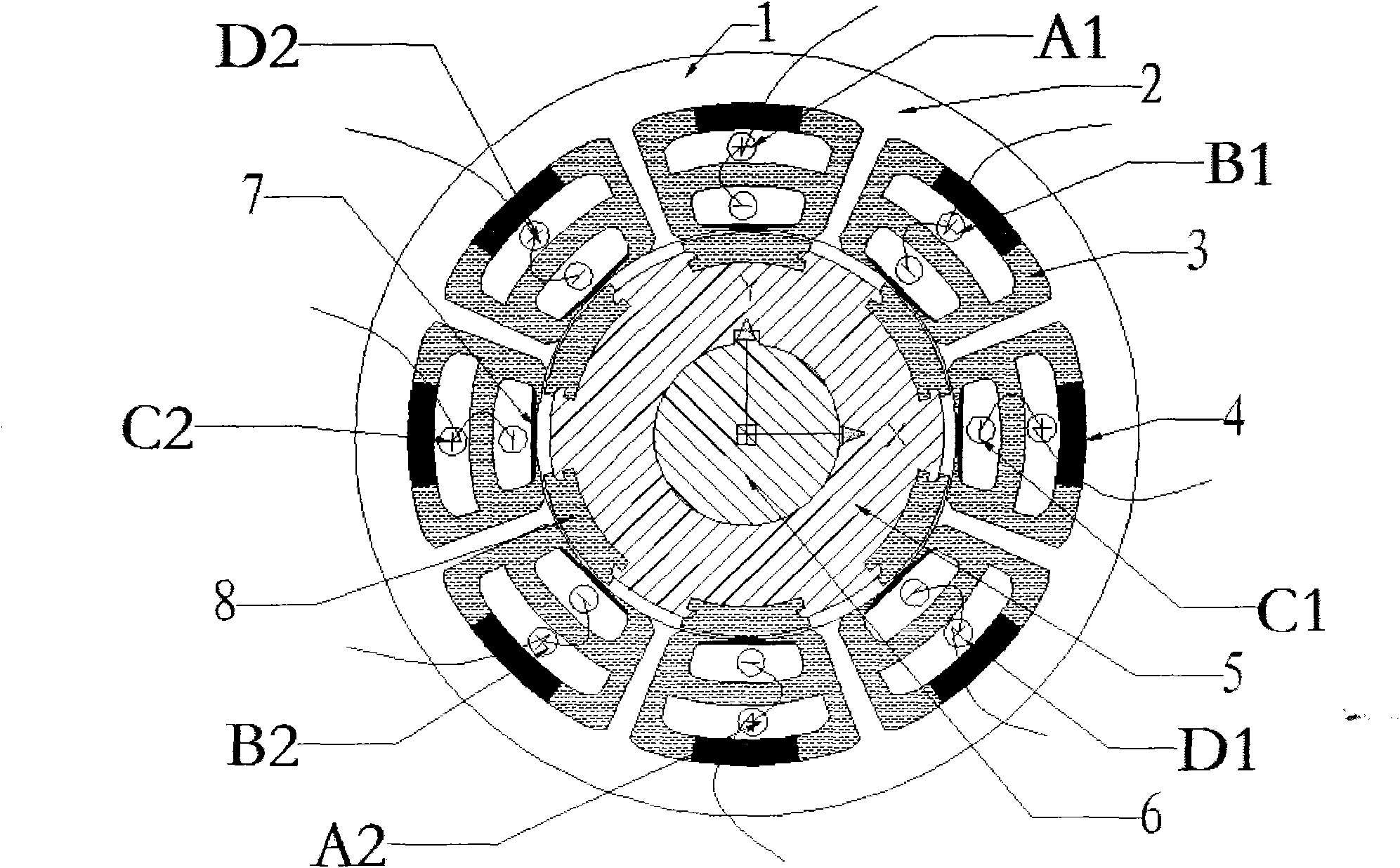
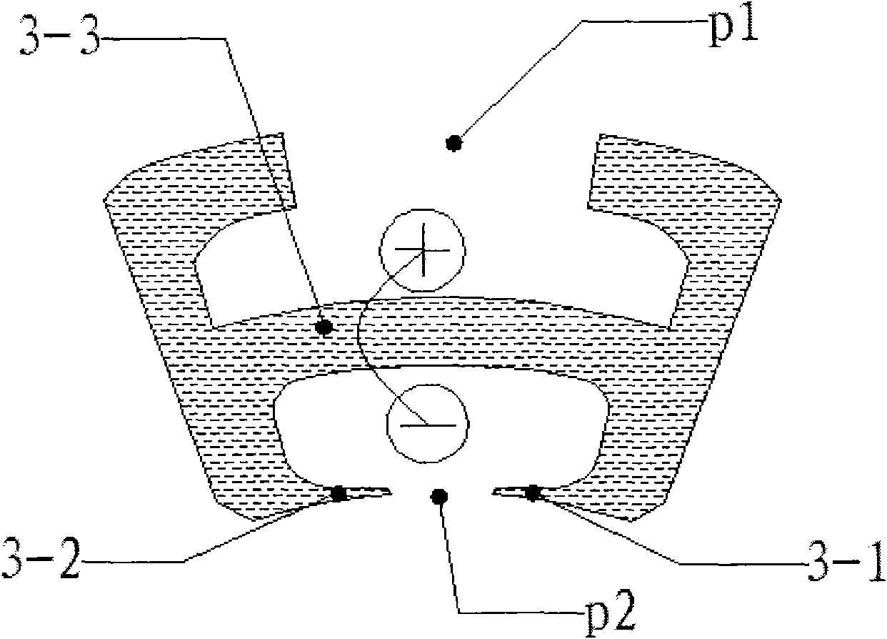
[0027] The core of the present invention is to re-plan the magnetic circuit and propose an H-shaped stator structure to prolong the service life of the permanent magnet and reduce the iron loss, thereby increasing the energy density; the same as the technical characteristics of the general motor, the hybrid excitation short-magnet of the present invention The road variable reluctance motor (1) also includes an organic base (2), a stator part, a rotor part and an excitation winding, but crucially, the stator part in the present invention includes a plurality of H-shaped stator segments (3) and is placed in each stator segment The first permanent magnet (4) at p1, the permanent magnets on each stator segment have opposite polarities, and the field windings (A1-A2, B1-B2, C1-C2, D1-D2) of each phase are embedded in each stator segment (3 ) in the stator slot.

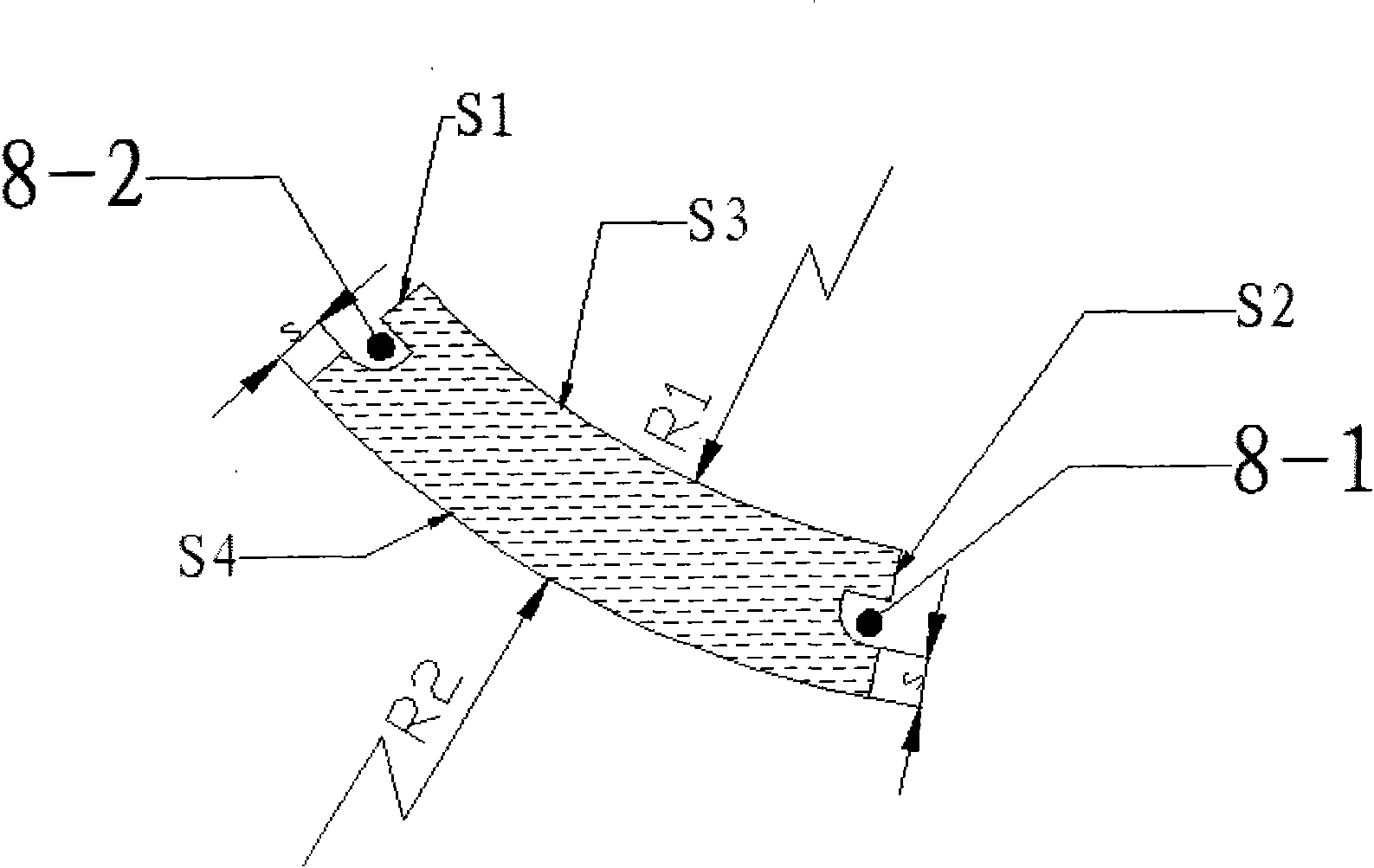
[0028] The rotor part includes a rotor body (5), a rotor segment assembly (8) and / or a second permanent magnet 4 (2), th...


PUM


Abstract

The invention discloses a mixed excitation short-magnetic-circuit variable-reluctance motor 1 as well as a stator structure and a rotor structure thereof. An inner circular face t of a base part 2 of the mixed excitation short-magnetic-circuit variable-reluctance motor is provided with modules 2-1 which protrude inwards in a preset interval angle; the stator part comprises a plurality of H-shaped stator sections 3 and first permanent magnets 4 (1) arranged at all the H-shaped stator sections p1, and the polarities of the permanent magnets of the stator sections are opposite; an exciting winding coil is embedded into two stator slots of each H-shaped stator section 3; and the rotor part comprises a rotor body 5 and a plurality of annular body rotor sections 8 arranged on the rotor body and/or second permanent magnets 4 (2), wherein the second permanent magnets are arranged on the s3 surfaces of the annular body rotor sections, and open grooves 8-1 and 8-2 are arranged on the lateral surfaces of the annular body rotor sections. According to the invention, the rotating force of the variable-reluctance motor can be increased, the energy density is improved, the torque ripple and the vibration and noise level are reduced, the performance is stable, and the size is smaller under the requirement of same output torque.

Description

technical field [0001] The invention relates to a motor, in particular to a mixed excitation short magnetic circuit variable reluctance motor, which belongs to the field of electric drive. Background technique [0002] The variable reluctance motor is a new type of speed regulating motor. The speed regulating system has the advantages of both DC and AC speed regulating systems. It is the latest generation of stepless speed regulating system following the frequency conversion speed regulating system and the brushless DC motor speed regulating system. It has attracted widespread attention due to its simple and solid structure, wide speed range, excellent performance, high efficiency and high reliability. [0003] The general variable reluctance motor includes a stator installed in the frame and a rotor that rotates relative to the stator. The stator and the rotor have protruding magnetic poles at a certain interval, and the number of magnetic poles of the stator and the rotor ...

Claims


Application Information

Patent Timeline
IPC IPC(8): H02K29/03H02K1/17H02K1/16H02K1/14H02K1/27
Inventor 周智庆迟永滨周智铭褚明张日红朱海飞骆李利
Owner SOUTH CHINA UNIV OF TECH
Why Eureka
Try Eureka