Method and system for combining a conversion between time-division multiplexed digital signals and packetized digital signals with a switching system interface

a switching system and digital signal technology, applied in the field of telecommunications, can solve the problems of increasing the cost and complexity, and increasing the complexity of the configuration

Inactive Publication Date: 2006-04-27
METASWITCH NETWORKS LTD
View PDF5 Cites 23 Cited by
  • Summary
  • Abstract
  • Description
  • Claims
  • Application Information

AI Technical Summary

Benefits of technology

[0018] It is a further object of this invention to combine an emergency standalone switching device that can route calls between subscribers in a serving area without the use of external switching equipment, and regardless of whether the subscribers are served by time-division multiplexed equipment or by any form of pack-based equipment or access network.
[0019] In accordance with the present invention, a conversion between time-division multiplexed digital signals and packetized digital signals with a switching system interface used to bypass the common control and switch matrix of a legacy class 5 digital switch is provided such that calls may be routed between time-division multiplexed equipment and a packet network, and that an emergency standalone switching device may route calls between subscribers within a serving area without the use of external switching equipment.

Problems solved by technology

However, the cost and complexity are increased by virtue of the fact that two types of network equipment must be purchased, installed, and administered.
The complexity of this configuration may be further increased if the softswitch that processes calls for the packet network controls both the media gateway and switching system interface.

Method used


Image

  • Method and system for combining a conversion between time-division multiplexed digital signals and packetized digital signals with a switching system interface
  • Method and system for combining a conversion between time-division multiplexed digital signals and packetized digital signals with a switching system interface
  • Method and system for combining a conversion between time-division multiplexed digital signals and packetized digital signals with a switching system interface

Examples


Embodiment Construction

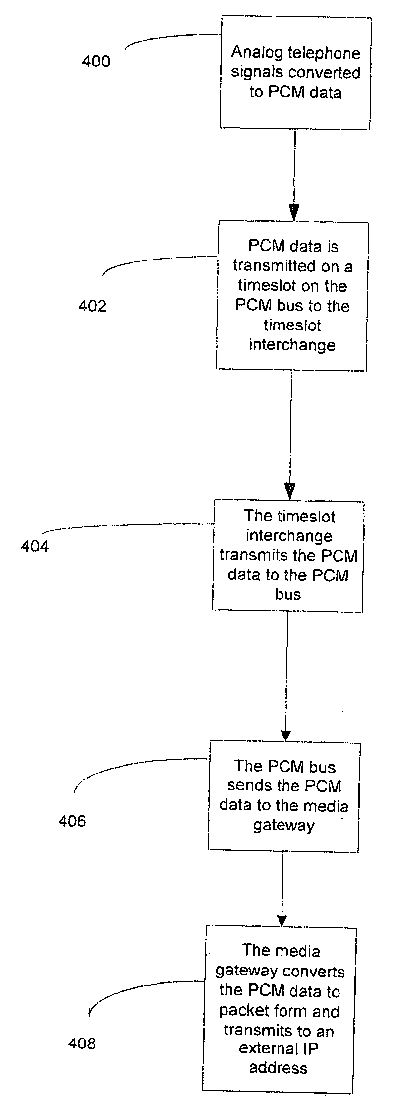
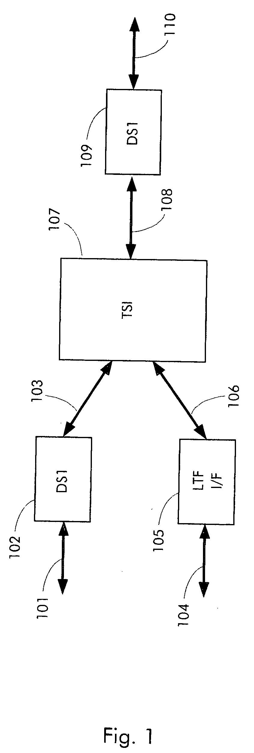
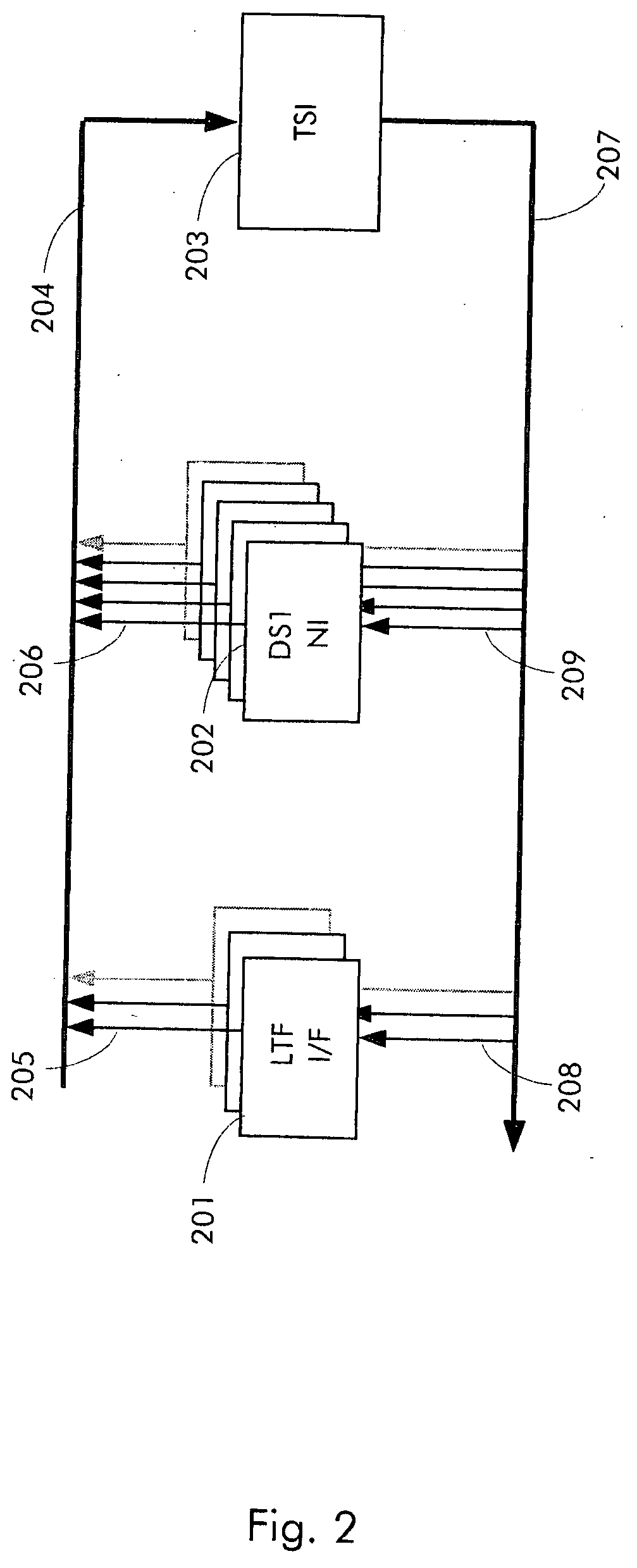
[0029] A system and method of providing a conversion between time-division multiplexed digital signals and packetized digital signals with a switching system interface utilized to bypass a common control and switch matrix of a digital switch is disclosed. FIG. 1 illustrates an exemplary embodiment of a switching system interface that couples the line / trunk frames of a legacy class 5 digital switch and DS1s serving DLCs to a host switch using a DLC protocol. One or more line / trunk interfaces 105 couple to legacy line / trunk frames via one or more connections 104. One or more DS1 interfaces 102 connect to one or more transmission facilities 101 that operate remote DLC equipment. In addition, one or more DS1 interfaces 109 connect to one or more transmission facilities 110 that connect, in turn, to a host digital switch or a media gateway. A time-slot interchange function 107 connects to the line trunk interfaces 105 and DS1 interfaces 102 and 109 via internal Pulse Code Modulation (PCM...


PUM


Abstract

The present invention is a switching system interface providing conversion between time-division multiplexed digital signals and packetized digital signals used to bypass a common control and switch matrix of a class 5 digital switch. The switching system interface includes a network interface for terminating a digital transmission facility that is part of a network architecture. In addition, the interface includes a line/trunk interface, compatible with the internal signals used to operate the line/trunk interface of the class 5 digital switching system and a switch, connected to the network interface and to the line/trunk interface, for routing data between network interfaces and line/trunk interface. The interface also converts the data between time-division multiplexed digital signals and packetized digital signals.

Description

RELATED APPLICATIONS [0001] This application is a continuation-in-part of a co-pending U.S. patent application Ser. No. 10 / 971,821 by David M. Smith entitled “METHOD AND SYSTEM FOR COMBINING AN EMERGENCY STANDALONE SWITCHING DEVICE WITH A SWITCHING SYSTEM INTERFACE,” filed Oct. 22, 2004 which claims the priority of U.S. Pat. No. 6,807,273 by David M. Smith entitled “METHOD AND APPARATUS FOR BYPASSING THE COMMON CONTROL AND SWITCH MATRIX OF A DIGITAL SWITCHING SYSTEM FOR TELECOMMUNICATIONS NETWORKS,” filed Nov. 30, 2001 and are hereby both incorporated in their entirety by reference herein.BACKGROUND OF THE INVENTION [0002] 1. Field of the Invention [0003] This invention relates to telecommunications. Specifically, the present invention relates to a system and method of providing a conversion between time-division multiplexed digital signals and packetized digital signals with a switching system interface utilized to bypass a common control and switch matrix of a digital switch. [000...

Claims


Application Information

Patent Timeline
Patent Type & Authority Applications(United States)
IPC IPC(8): H04M3/00H04J3/16H04M5/00
CPCH04L12/66H04L65/1053H04Q2213/13034H04Q2213/13292H04Q2213/13296H04Q2213/1334H04Q2213/13341H04Q2213/13393
Inventor SMITH, DAVID M.
Owner METASWITCH NETWORKS LTD
Why Eureka
Try Eureka