Removable footwear traction plate

a technology of traction plate and removable footwear, which is applied in the direction of fastenings, footwear, apparel, etc., can solve the problems of not providing arbitrary rotational orientation of traction elements with respect, and footwear traction approaches that do not provide for removable traction structures

Active Publication Date: 2006-05-04
CLEATS
View PDF14 Cites 58 Cited by
  • Summary
  • Abstract
  • Description
  • Claims
  • Application Information

AI Technical Summary

Benefits of technology

[0008] In another embodiment of the invention, a shoe-coupling element is provided that is removably attachable to the flange. The shoe-coupling element is attachable to the corresponding receptacle in the shoe by a rotation of no more than 360 degrees. In other embodiments of the invention, the element is attachable to the corresponding receptacle by rotation of not more than 270, 180, or 120 degrees respectively. This arrangement advantageously allows the traction plate and the shoe-coupling element to rotate independently so that a desired orientation of the traction plate with respect to the outsole may be achieved.

Problems solved by technology

Such approaches to footwear traction do not provide for removable traction structures that are larger than can be secured to the shoe effectively by a single closure.
Further, these approaches do not allow for an arbitrary rotational orientation of the traction element with respect to the shoe outsole.

Method used


Image

  • Removable footwear traction plate
  • Removable footwear traction plate
  • Removable footwear traction plate

Examples


Embodiment Construction

[0021] Definitions. As used in this description and the accompanying claims, the following terms shall have the meanings indicated, unless the context otherwise requires:

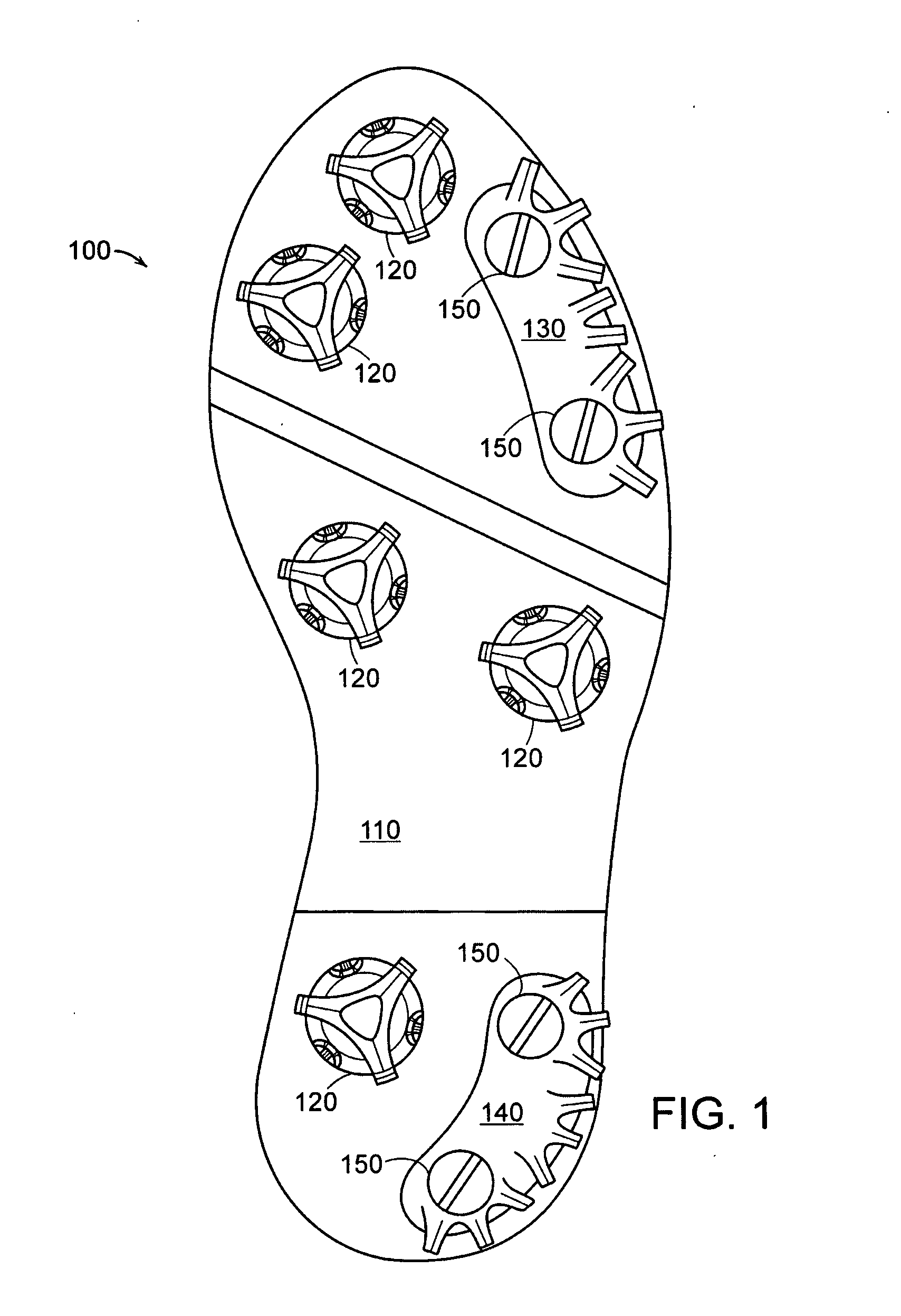
[0022] A “shoe” means any outer covering for a foot including, without limitation, athletic footwear, sandals, boots, and slippers.

[0023] A “flange” means any generally planar object. A flange may be solid or web-like or any combination of portions that are solid or web-like. A flange comprises any planar geometry including concave portions or convex portions or combinations of concave and convex portions.

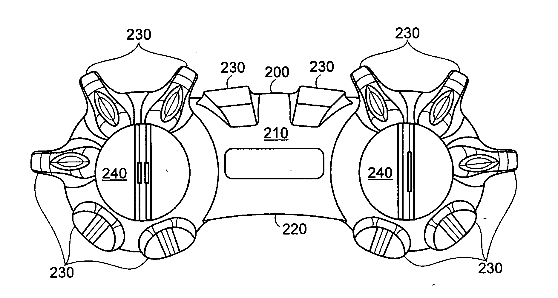
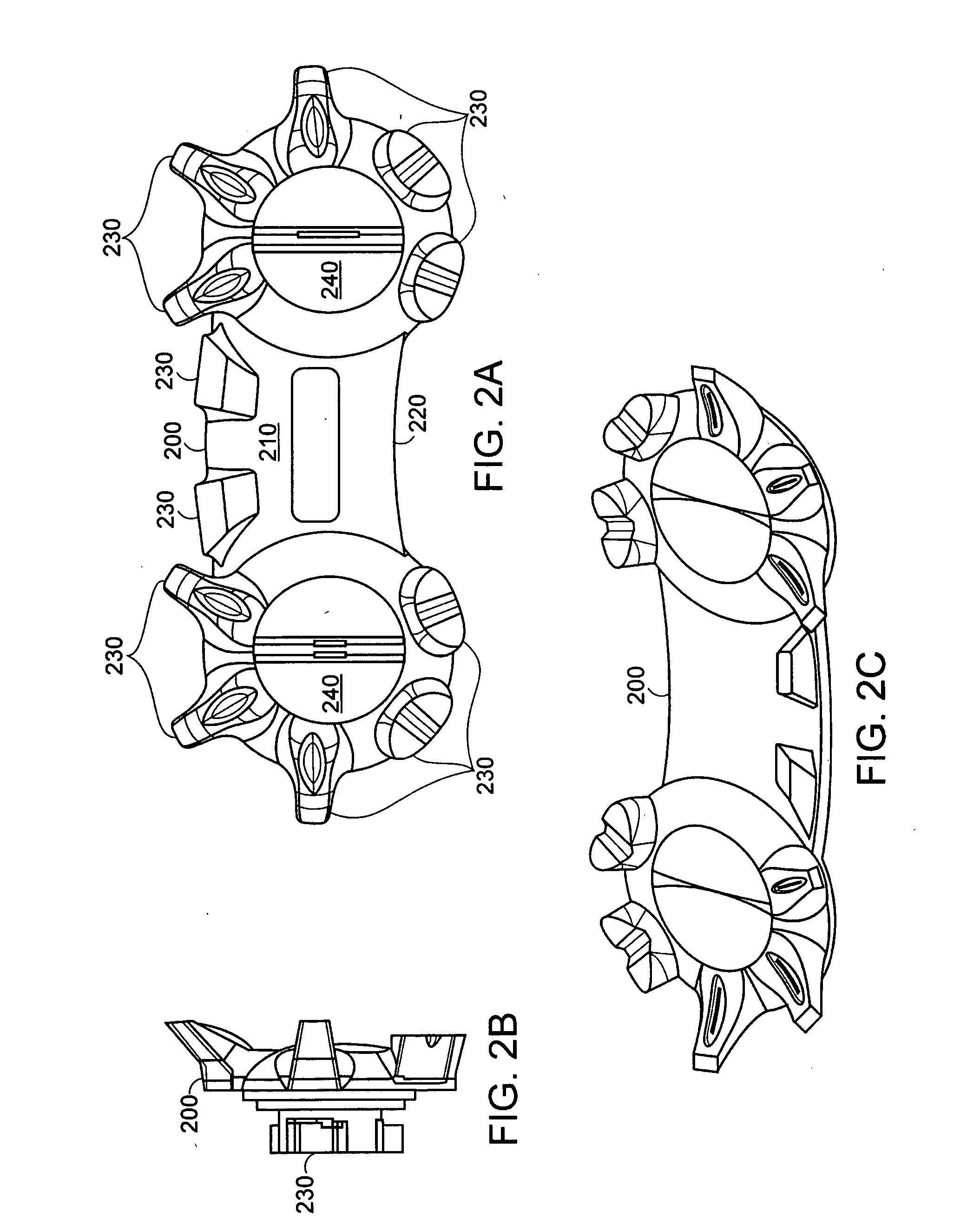
[0024] A “surface-engaging element” is any physical configuration that provides traction when contacting a surface. Surface-engaging elements may include, without limitation, any of the protrusions known in the art for that purpose including any of the protrusions or combinations of protrusions taught in U.S. Pat. Nos. D320882, D454248, D468895, D493276, 6,023,860, 6,041,526, 6,052,923, 6,327,797, 6,354,021, 6,4...


PUM


Abstract

A traction plate for a shoe. The traction plate is removably attachable to the outsole of a shoe to provide traction on a surface for a shoe wearer. The plate includes a flange with one or more surface-engaging elements on one face. The plate also includes two or more shoe-coupling elements. The shoe-coupling elements are inserted into corresponding receptacles in a shoe-outsole and then rotated to affix the plate to the shoe. The shoe-coupling elements may be captively attached to the plate flange or attachable to the shoe receptacle with a rotation of no more than one full revolution.

Description

[0001] This application claims priority from U.S. provisional patent application No. 60 / 587,158, filed Jul. 12, 2004, entitled “Removable Footwear Traction Plate,” which is incorporated herein by reference.TECHNICAL FIELD [0002] The present invention relates to traction gear mounted on the bottom of footwear, in particular, athletic footwear. BACKGROUND [0003] Conventional traction gear for footwear use a large number of individual traction elements, such as cleats, that are attached to the outsole of a shoe. The typical golf shoe, for example, includes seven cleats that are individually attached to the shoe by screwing the cleat into the mated receiving receptacle in the bottom of the footwear. Progress has been made in recent years in reducing the effort needed to attach and to remove traction elements from footwear by reducing the rotations needed to attach each traction element. For example, U.S. Pat. No. 5,768,809 describes a quick-release Q-LOK™ traction element connector. Whe...

Claims


Application Information

Patent Timeline
Patent Type & Authority Applications(United States)
IPC IPC(8): A43C15/00A43B5/00
CPCA43B13/141A43B13/26A43C15/02A43C15/162A43C15/161
Inventor SAVOIE, ARMAND J.YUE, WILSON
Owner CLEATS
Why Eureka
Try Eureka