
Microphone diaphragms defined by logarithmic curves and microphones for use therewith

Inactive Publication Date: 2006-05-04
CARDAS AUDIO
View PDF7 Cites 34 Cited by
  • Summary
  • Abstract
  • Description
  • Claims
  • Application Information

AI Technical Summary

Problems solved by technology

This results in dimensional and dynamic duplications in the mounted diaphragm and complicates the process of signal absorption and reflection.

Method used


Image

  • Microphone diaphragms defined by logarithmic curves and microphones for use therewith
  • Microphone diaphragms defined by logarithmic curves and microphones for use therewith
  • Microphone diaphragms defined by logarithmic curves and microphones for use therewith

Examples


Embodiment Construction

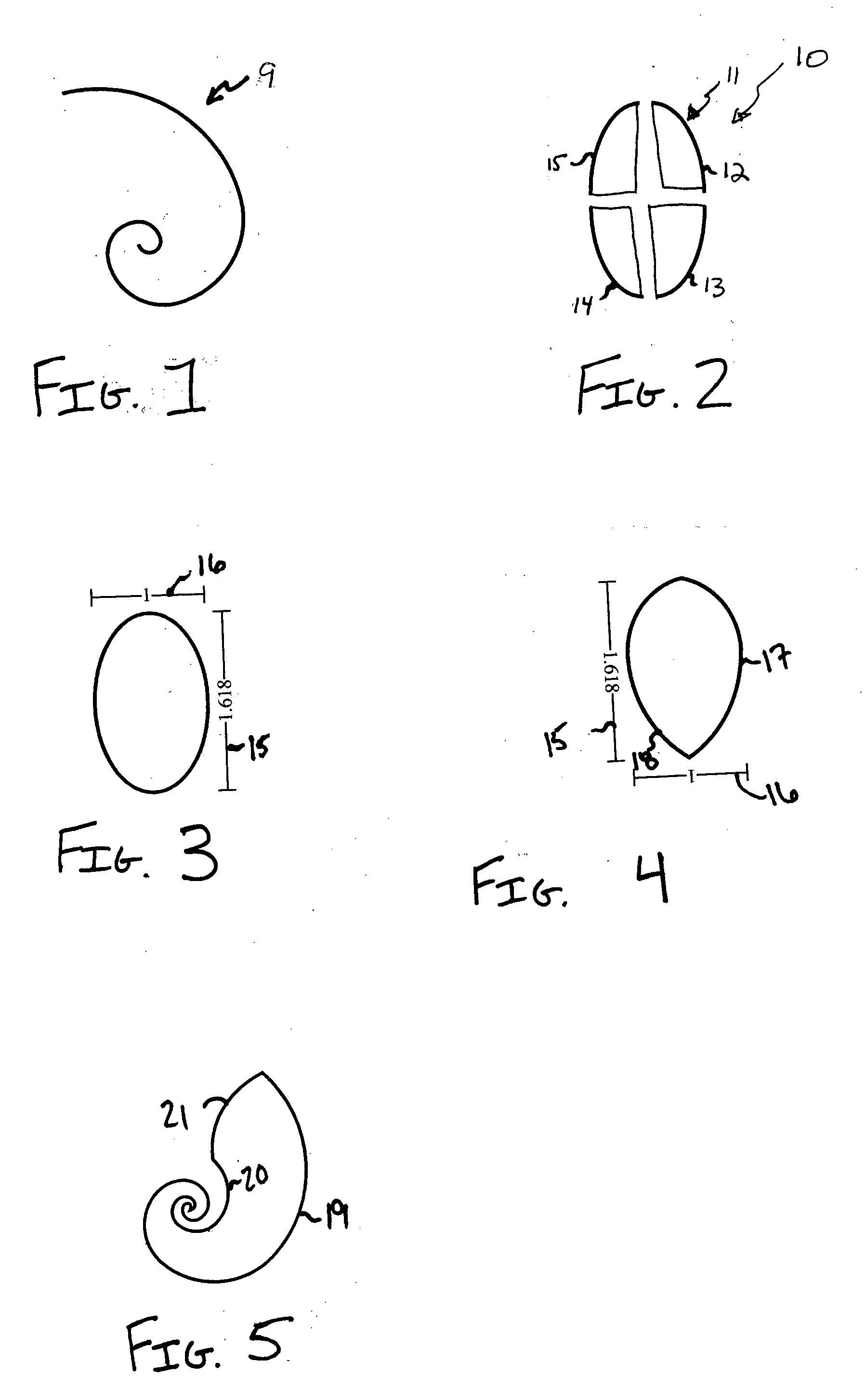
[0016] The present invention provides microphone diaphragms where the peripheral edge or periphery of the diaphragm is defined, at least in part, by a logarithmic curve, as that term is defined herein. In particular, the shapes of the microphone diaphragm of the present invention are derived at least in part from sections of a golden spiral, as that term is defined herein.

[0017] A “logarithmic curve” as used herein may generally be expressed in polar notation as r=ae(kθ); where r is the distance from an origin, θ is the angle the graph is open to, and a and k are constants.

[0018]FIG. 1 depicts a golden spiral 9. A “golden spiral”, as used herein, is mathematically expressed as a logarithmic curve having a value of k where the lengths of the portions of the axes cut off by the spiral fit the golden ratio. The golden ratio, as used herein and known in the art, is (1+√5)2≈1.618. The golden ratio is also referred to by the Greek symbol phi, φ. Accordingly, for a golden spiral, k=(2 / π)...


PUM


Abstract

Microphone diaphragms are provided having an active area with a periphery defined by at least a portion of a logarithmic curve. In some embodiments, the periphery is defined by at least a portion of a golden spiral. The microphone diaphragms may be used in pressure microphones.

Description

TECHNICAL FIELD [0001] The present invention relates to microphone diaphragms. BACKGROUND OF THE INVENTION [0002] Presently, diaphragm microphones use round or rectangular diaphragm mounting structures. These round or rectangular shapes have recurring cord lengths between their peripheral edges that result in predictable resonance and phase shifts in their transduced signals. Briefly, perpendicular lines from opposing peripheral edges of the circular or rectangular structures converge on a common point or line. This results in dimensional and dynamic duplications in the mounted diaphragm and complicates the process of signal absorption and reflection. Accordingly, microphones employing round or rectangular microphone diaphragms exhibit grouped time delays and native resonances. [0003] There is therefore a need for a microphone diaphragm that smoothes signal absorption and reflection, reducing group time delays and native resonances seen in present microphones. SUMMARY OF THE INVENTI...

Claims


Application Information

Patent Timeline
IPC IPC(8): H04R7/00G10K13/00
CPCH04R7/00H04R7/02
Inventor CARDAS, GEORGE
Owner CARDAS AUDIO
Learn More