Interactive vehicle display system

a vehicle display and interactive technology, applied in the direction of static indicating devices, instruments, dashboard fitting arrangements, etc., can solve the problems of not being able to focus on small features of the display, being very distracting, and having the potential to add many more functions, so as to optimize the reception of voi

Inactive Publication Date: 2006-10-24
AMERICAN VEHICULAR SCI
View PDF68 Cites 350 Cited by
  • Summary
  • Abstract
  • Description
  • Claims
  • Application Information

AI Technical Summary

Benefits of technology

[0156]Instead of adjusting the seat, the projecting means can be adjusted based on the desired location of the occupant's eyes relative to the text and/or graphics. That is, adjustment means are coupled to the projecting means for adjusting the projecting means based on the determined desired location of the eyes of the occupant relative to the projected text and/or graphics to thereby enable the occupant's view of the projected text and/or graphics to be improved.
[0157]The invention also encompasses a vehicle including the above-described determining means, adjustment means and projecting means with the interacting means being an optional modification. In this case, the projecting means and/or seat would be adjusted to ensure that the eyes of the occupant are in the eye-ellipse an...

Problems solved by technology

A vehicle driver is not going to be able to focus intently on small features of the display.
On the other hand, the potential exists for adding many more functions, some of which may become very distracting.
It is envisioned, therefore, that implementation of the system will be in stages and to a large degree will be concomitant with the evolution of other safety systems such as autonomous vehicles.
Most of the capacitance technologies described require the conductivity of the operator's finger and therefore will not functions if the driver is wearing gloves.
For thicker gloves, the projected capacitive systems become necessary with an additional loss of resolution.
Thin metal oxide films on thin plastic films can also be used, however, the durability of this system can be a serious problem.
This requirement may also be incompatible with an airbag deployment doors unless the pad is placed wholly on one flap of the ...

Method used


Image

  • Interactive vehicle display system
  • Interactive vehicle display system
  • Interactive vehicle display system

Examples


Embodiment Construction

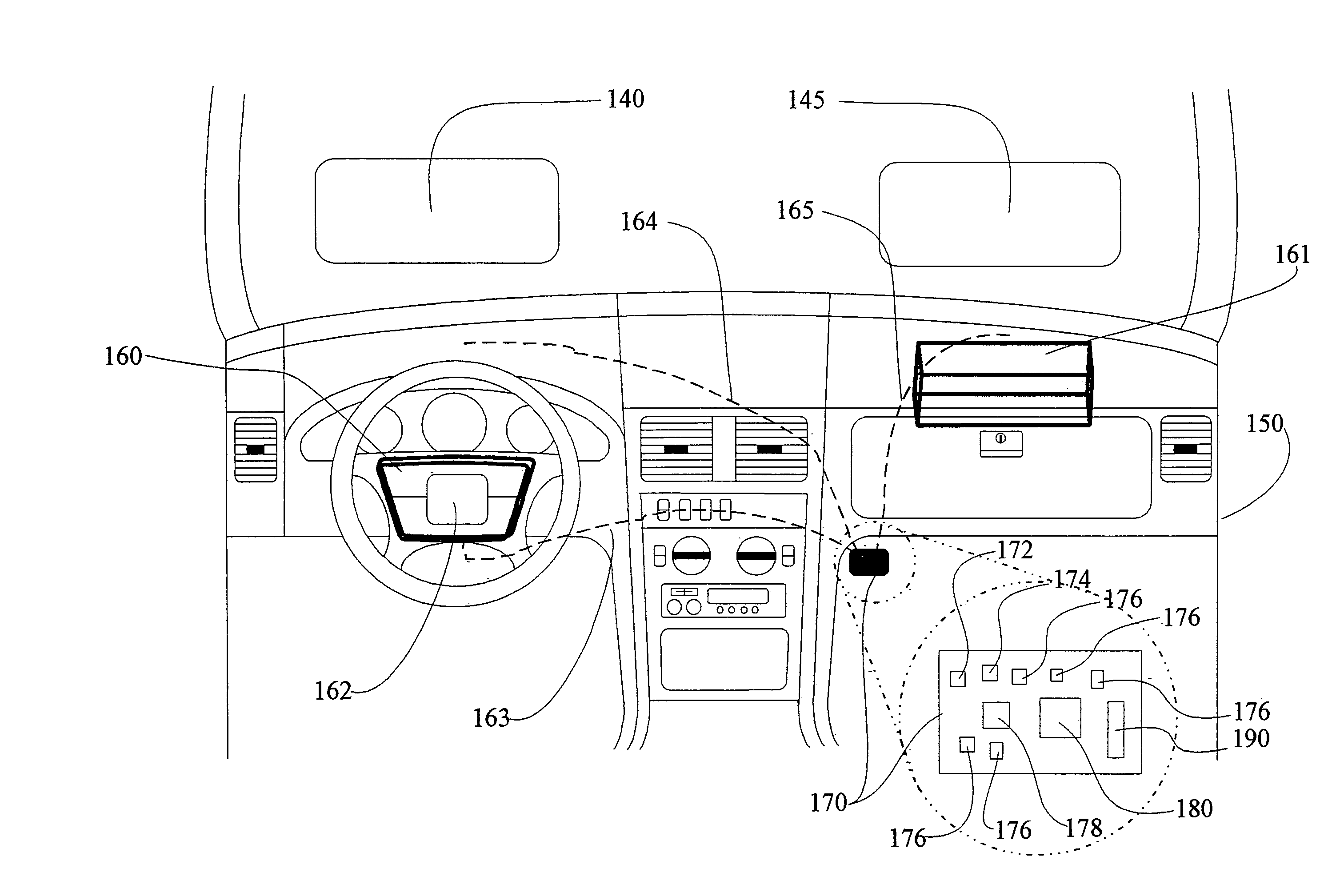
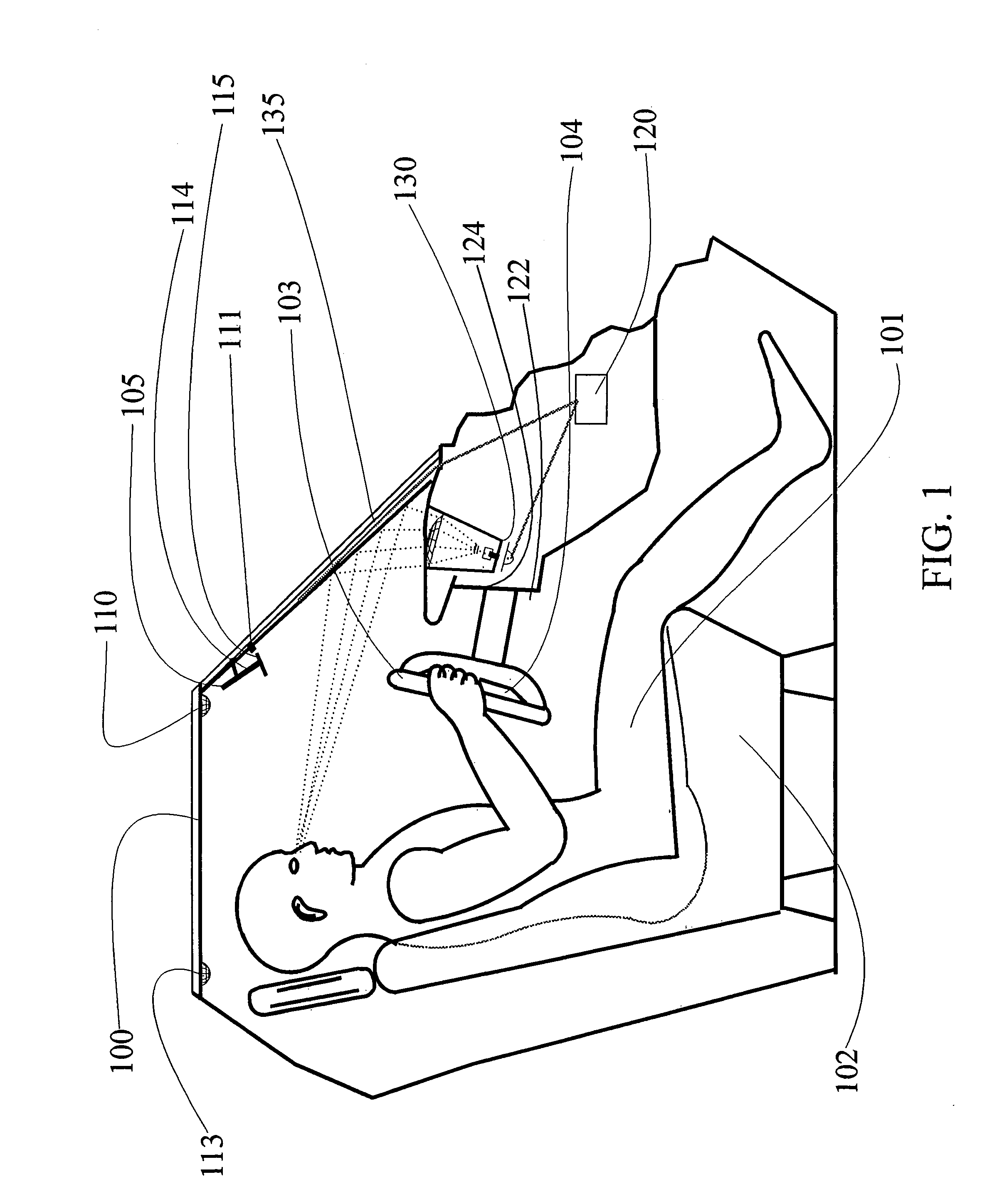
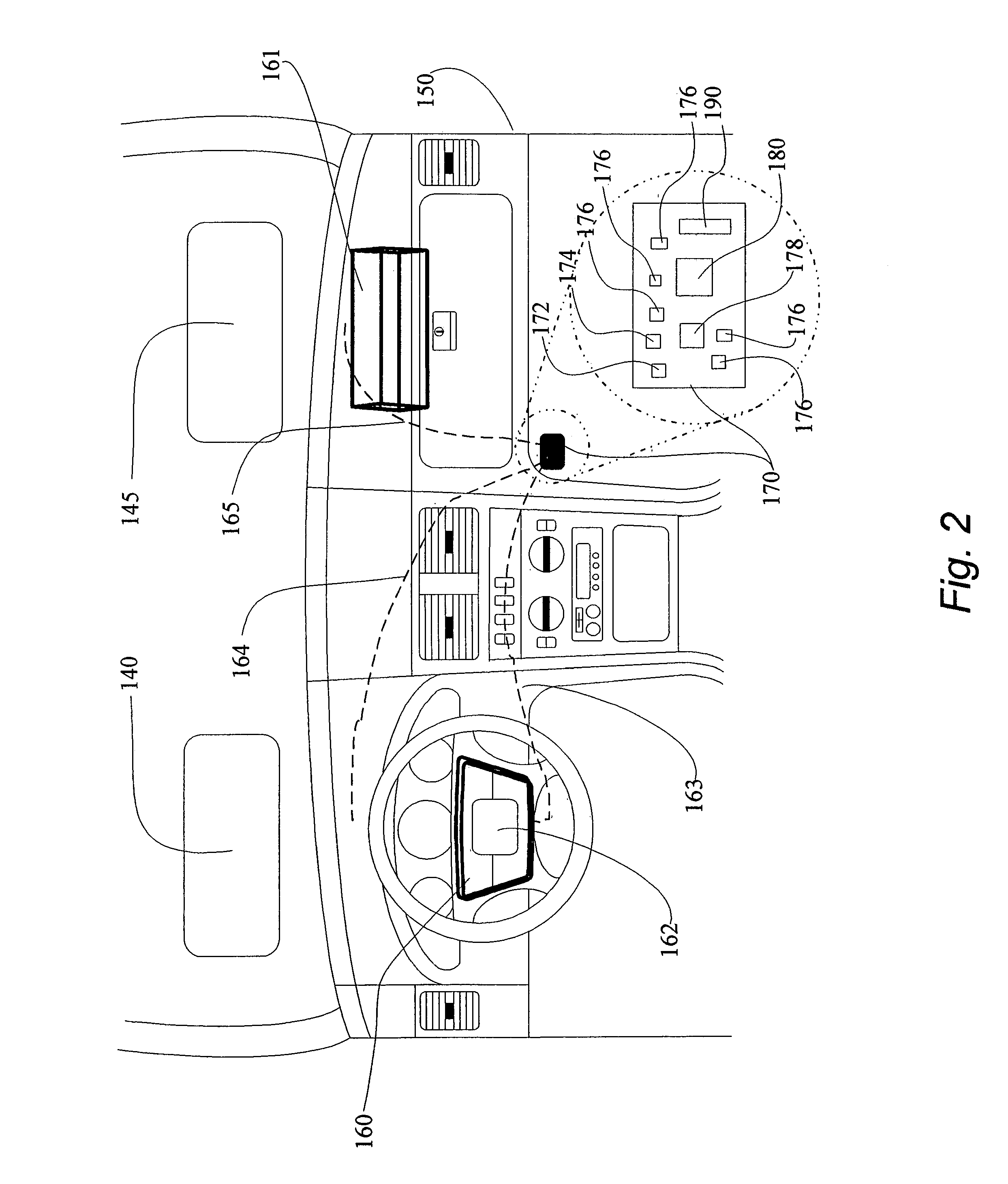
[0181]Referring now to the drawings wherein like reference numerals refer to the same or similar elements, a section of the passenger compartment of an automobile is shown generally as 100 in FIG. 1. A driver 101 of the automobile sits on a seat 102 behind a steering wheel 103 that contains an airbag assembly 104 with a touch pad data entry device, not shown. A heads up display (HUD) 130 is positioned in connection with instrument panel 124 and reflects off of windshield 135. Three transmitter and / or receiver assemblies (transducers) 110, 111, and 113 are positioned at various places in the passenger compartment to determine the height and location of the head of the driver relative to the heads up display 130. Only three such transducers are illustrated in FIG. 1. In general, four such transducers are used, however, in some implementations as few as two and as many as six are used for a particular vehicle seat.

[0182]FIG. 1 illustrates several of the possible locations of such occup...


PUM


Abstract

An interactive display system for a vehicle including a heads up display system for projecting text and/or graphics into a field of view of a forward-facing occupant of the vehicle and an occupant-controllable device enabling the occupant to interact with the heads up display system to change the text and/or graphics projected by the heads up display system or direct another vehicular system to perform an operation. The device may be a touch pad arranged on a steering wheel of the vehicle (possibly over a cover of an airbag module in the steering wheel) or at another location accessible to the occupant of the vehicle. A processor and associated electrical architecture are provided for correlating a location on the touch pad which has been touched by the occupant to the projected text and/or graphics. The device may also be a microphone.

Description

CROSS-REFERENCE TO RELATED APPLICATION[0001]This application claims priority under 35 U.S.C. §119(e) of U.S. provisional patent application Ser. No. 60 / 170,973 filed Dec. 15, 1999.FIELD OF THE INVENTION[0002]This invention relates in general to an interactive vehicle display system and in particular, to a heads up display system which is combined with a steering wheel mounted touch pad or voice input system to permit the vehicle operator to operate various apparatus, including a personal computer, without taking his or her eyes off of the road.BACKGROUND OF THE INVENTION[0003]In an existing heads up display, information is projected onto a specially treated portion of the windshield and reflected into the eyes of the driver. An important component of a head-up display system is known as the combiner. The combiner is positioned forward of the driver and extends partly across his or her view of the real world scene. It is usually either on the interior surface of or laminated inside o...

Claims


Application Information

Patent Timeline
IPC IPC(8): G09G5/08G02B27/00G02B27/01
CPCB60K35/00B60K37/06G02B27/01B60K2350/1036B60K2350/2039G02B2027/014G02B2027/0187B60K2370/1446B60K2370/34B60K2370/785
Inventor BREED, DAVID S.
Owner AMERICAN VEHICULAR SCI
Why Eureka
Try Eureka