Printing of radiation curable inks into a radiation curable liquid layer

a liquid layer and radiation curable technology, applied in pattern printing, printing, other printing apparatus, etc., can solve the problems of not being a viable solution in an industrial printing environment, changing inks in printers and print heads is very time-consuming, and the resolution of printed images is accurately controlled.

Inactive Publication Date: 2006-05-04
AGFA NV
View PDF20 Cites 40 Cited by
  • Summary
  • Abstract
  • Description
  • Claims
  • Application Information

AI Technical Summary

Benefits of technology

[0028] It is an object of the present invention to provide a printing process wherein the resolution of a printed image is accurately controlled on a wide variety of ink-receivers.
[0029] It is an another object of the present invention to provide a printing process delivering images exhibiting a high and uniform gloss.
[0031] It was surprisingly found that by providing a substrate with a radiation curable liquid layer and uniformly adjusting the thickness of this liquid layer, that ink-jet images of high quality could be produced on a wide variety of substrates.

Problems solved by technology

Hot melt inks are limited to thermally stable ink-receivers, while radiation curable inks can be jetted on a wide variety of ink-receivers.
The main problem of radiation curable inks is that the image quality tends to change with the selection of the ink-receiver.
However, changing inks in printer and print head is very time consuming and not really a viable solution for an industrial printing environment.
Corona discharge treatment and plasma treatment increases the cost, complexity and maintenance of the equipment used to process the substrates.
Substrates may contain significant impurities or irregularities that may interfere with the treatment of the substrate.
Another problem associated with radiation curable ink-jet printing is that images exhibit a poor gloss compared to solvent or aqueous based inks on an absorbing substrate.
Beside restrictions on the arrangements of print heads and the calculating power required to achieve the variation of thickness in accordance with the image to be printed, it is also difficult to avoid the spreading of undercoat layer from unprinted area's, i.e. full thickness of the undercoat layer, into the area's printed with 100% ink, i.e. zero thickness of undercoat layer, which results in less sharp images.
Although surface property modification by either coating or pre-treatment techniques has been widely employed, the exact nature of the ink-media interaction is not fully understood.
Attempts are typically made to correlate the print quality to measurable surface parameters such as surface energy and surface roughness, but these parameters do not fully capture the behaviour of ink droplets on various media.

Method used


Image

  • Printing of radiation curable inks into a radiation curable liquid layer
  • Printing of radiation curable inks into a radiation curable liquid layer

Examples


example 1

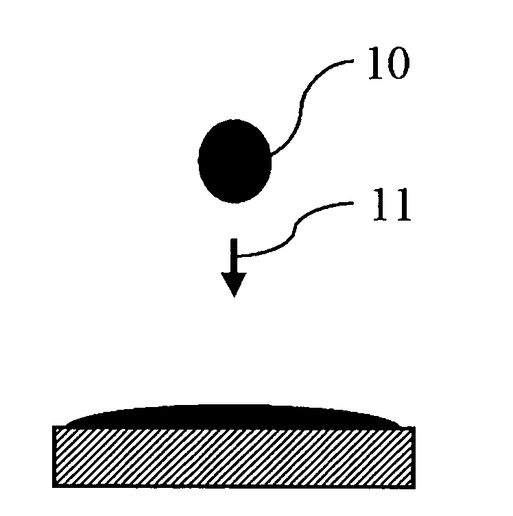
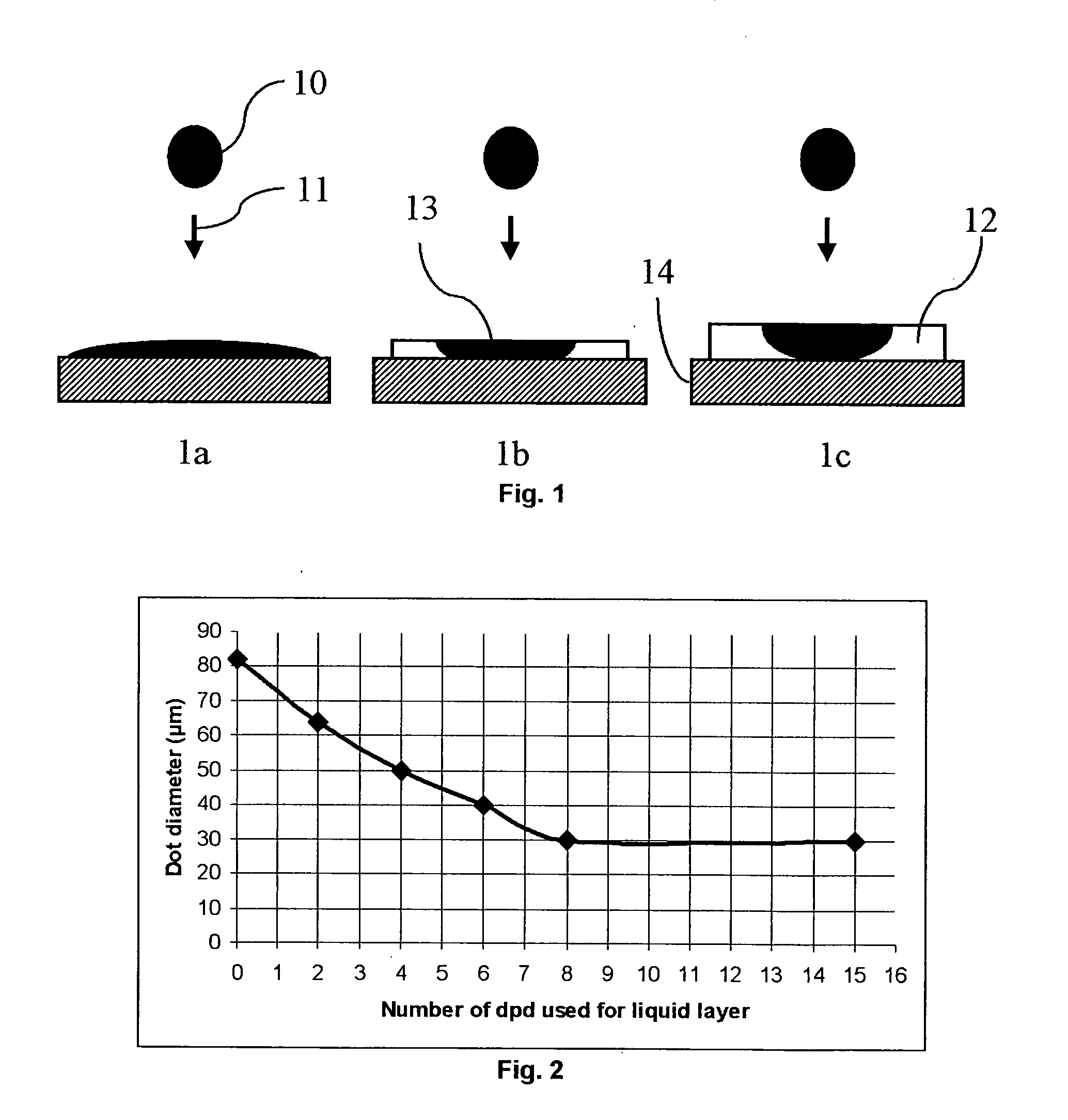
[0208] This example illustrates how the dotsize of a ink droplet is controlled by the thickness.

Preparation of Radiation Curable Liquid Layer

[0209] A colourless radiation curable liquid layer composition Ink-L was prepared according to Table 1 by mixing the ingredients and stirring for one hour to ensure that all components were well distributed. The weight % (wt %) was based on the total weight of the radiation curable liquid layer composition.

TABLE 1wt % of:Ink-LDPGDA ™66.5Irgacure ™ 9072.5Darocur ™ ITX5.0Craynor ™ CN 50125.0Byk ™-3331.0

[0210] The radiation curable liquid layer composition INK-L was jetted on PET with a custom built ink-jet printer equipped with a UPH print head from AGFA to produce the ink receivers IR-2 to IR-7. A resolution of 360×360 dpi was used to print in a number of dpd (droplets per dot) as indicated by Table 2, wherein 1 dpd is equal to a droplet volume of 3 pL.

TABLE 2Ink receiver# dpd of Liquid layerIR-10IR-22IR-34IR-45IR-56IR-68IR-715

Preparatio...

example 2

[0216] In this example the dotsize of ink-jet inks jetted on the liquid layer after curing was evaluated.

[0217] An ink receiver IR-8 was prepared in the same manner as the ink receiver IR-7 of Example 1, except that the radiation curable ink-jet ink INK-M was used instead of INK-L. The ink receiver IR-5 of Example land the ink receiver IR-8 were first cured using a Fusion DRSE-120 conveyer, equipped with a Fusion VPS / 1600 lamp (D-bulb), which transported the ink receivers under the UV lamp on a conveyer belt at a speed of 20 m / min.

[0218] On the cured ink receivers IR-5 and IR-8, 1 dpd of the radiation curable ink-jet inks INK-M and INK-C were jetted at a resolution of 360×360 dpi with the custom built ink-jet printer. The printed samples were cured by the same procedure as used for curing the ink receivers IR-5 and IR-8. The radiation curable ink INK-M was not jetted on the ink receiver IR-8 since visual differentiation would be difficult. The dotsize was determined for each cured...

example 3

[0220] In this example the coalescence and gloss was evaluated.

Preparation of Radiation Curable Liquid Layer

[0221] A colourless radiation curable liquid layer composition Ink-L2 was prepared according to Table 6 by mixing the ingredients and stirring for five minutes. The weight % (wt %) was based on the total weight of the radiation curable liquid layer composition.

TABLE 6Wt % of:INK-L2Craynor ™ CN50170.0Irgacure ™ 50016.7Craynor ™ CN 3868.3Irgacure ™ 18703.3Byk ™-3331.7

Evaluation of the Properties

[0222] With the custom build printer equipped with a UPH head from AGFA the radiation curable liquid layer composition INK-L2 was jetted at 8 dpd and 360×360 dpi on half of the surface of a PET film. In a comparative sample COMP-1, the radiation curable inkjet ink INK-M was jetted onto the PET film, while in an inventive sample INV-1, the radiation curable inkjet ink INK-M was jetted into the liquid layer on the other half of the PET film. After UV-curing (Fusion VPS / 1600 lamp (D-b...


PUM


Abstract

A printing process is disclosed for ink-jet printing a radiation curable image on a substrate (14). First a radiation curable liquid layer (12) is provided on at least a portion of the substrate (14). Radiation curable ink-jet ink droplets (10) are jetted into the radiation curable liquid layer (12) and the radiation curable liquid layer (12) containing the radiation curable ink-jet ink droplets (13) is then cured. The resolution of the radiation curable image is controlled by uniformly adjusting the thickness of the liquid layer (12) for the dotsize of the radiation curable ink-jet ink jetted onto the cured layer.

Description

CROSS-REFERENCE TO RELATED PATENT APPLICATIONS [0001] This application claims the benefit of U.S. Provisional Application No. 60 / 630,107 filed Nov. 22, 2004, which is incorporated by reference. In addition, this application claims the benefit of European Application No. 04105394 filed Oct. 29, 2004, which is also incorporated by reference.TECHNICAL FIELD [0002] The present invention relates to the printing of radiation curable inks into a radiation curable liquid layer, more specifically to high-speed ink-jet printing exhibiting high image quality. BACKGROUND ART [0003] In ink-jet printing,tiny drops of ink fluid are projected directly onto an ink-receiver surface without physical contact between the printing device and the ink-receiver. The printing device stores the printing data electronically and controls a mechanism for ejecting the ink drops image-wise onto the ink-receiver. Printing can be accomplished by moving a print head across the ink-receiver or vice versa. [0004] The i...

Claims


Application Information

Patent Timeline
Patent Type & Authority Applications(United States)
IPC IPC(8): B41J2/01
CPCB41J2/2114B41J2/2117B41M7/0081B41M3/008B41J11/002B41J11/00214
Inventor CLAES, ROLANDJANSSENS, ROBERT
Owner AGFA NV
Why Eureka
Try Eureka