
Powder pump flow monitoring method and system

Inactive Publication Date: 2006-05-04
NORDSON CORP
View PDF48 Cites 37 Cited by
  • Summary
  • Abstract
  • Description
  • Claims
  • Application Information

AI Technical Summary

Benefits of technology

[0012] Furthermore, a very small drop in the flow rate or flow volume of the compressed air in the compressed air feed line can also be caused by a gradual decrease in the permeability of a particle filter, which is installed between each chamber and the compressed air feed line in the previously known pumps. The purpose of this particle filter is to prevent backflow of pulverulent material into the line when separate sections of the line between the chambers and a multiple-way control valve are alternately used as a compressed air feed line and a vacuum line for drawing pulverulent material into the chambers by applying a vacuum to the chambers. Therefore, in another advantageous embodiment of the invention, this gradual decrease is used t

Problems solved by technology

Since the spray guns are moved around the objects to be coated by the operating personnel during the powder coating operation to achieve uniform powder application, and the hose lines must be pulled along during this operation, kinks can sometimes develop in the hose lines, which can lead to obstruction of the lines due to the associated narrowing of the cross section.
This causes an interruption or disruption of the work flow and makes it necessary to blow out the clogged lines, which results in wasted time and labor.
Similar problems can also arise with automatic spray application devices if the hose lines leading to these devices are poorly installed.
If the tube becomes clogged with powdered talc in the vicinity of the extrusion die during this process, the obstruction travels away from the extrusion die at a high speed.
If the operator of the extruder does not detect the obstruction quickly enough, it becomes necessary to cut large sections of the extruded tube out of the finished tube strand and to discard them as unusable.
If the pipe system becomes completely obstructed, this manifests itself in an abrupt drop in the flow rate of the compressed air, since this type of obstruction generally occurs suddenly.
Furthermore, a very small drop in the flow rate or flow volume of the compressed air in the compressed air feed line can also be caused by a gradual decrease in the permeability of a particle filter, which is installed between each chamber and the compressed air feed line in the previously known pumps.
Furthermore, the installation of the flowmeter on the clean-air side can prevent contamination by the conveyed powder particles, which is unavoidable when the sensors are installed in the pipe system after the feed pump.

Method used


Image

  • Powder pump flow monitoring method and system
  • Powder pump flow monitoring method and system
  • Powder pump flow monitoring method and system

Examples


Embodiment Construction

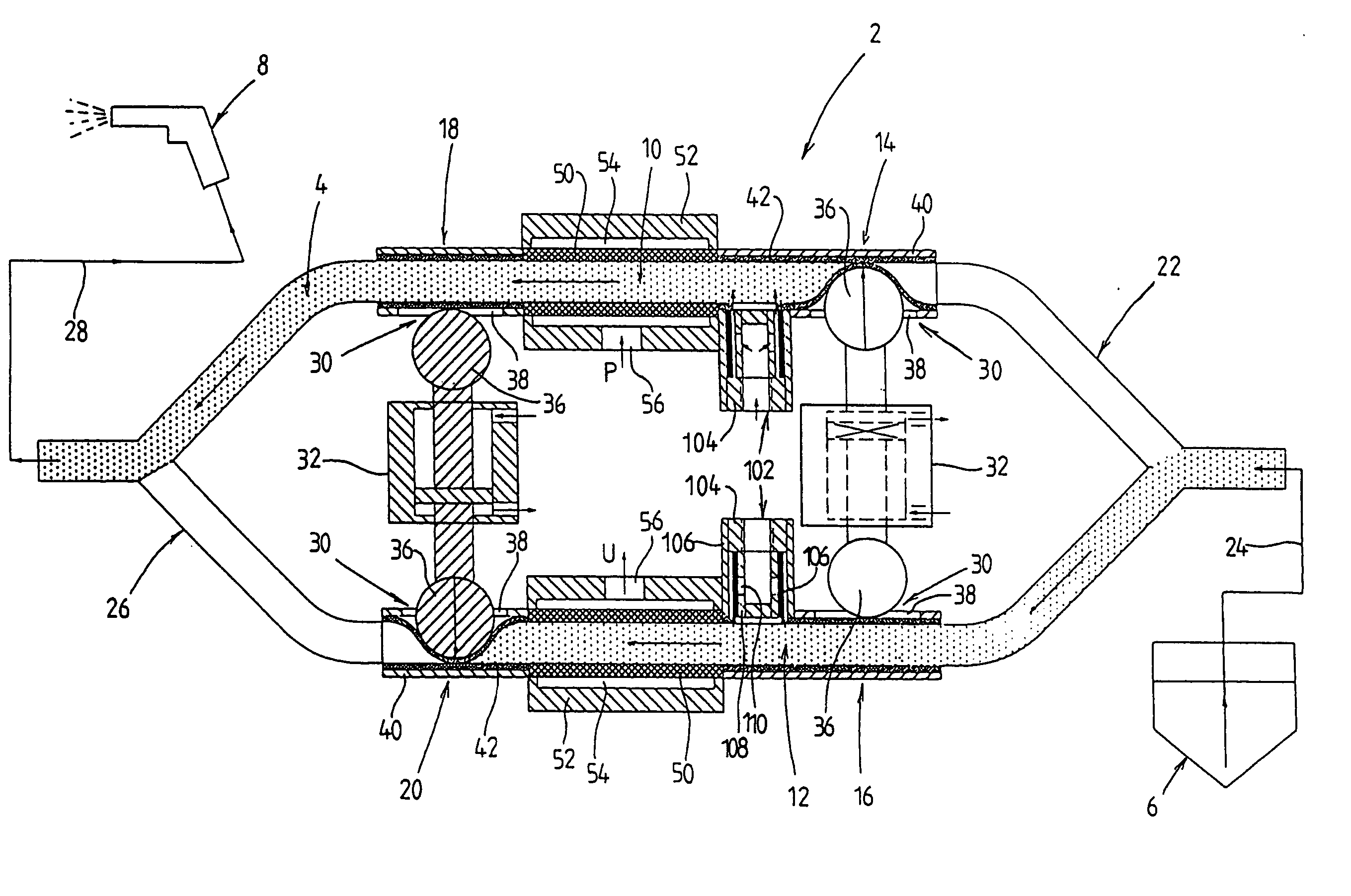
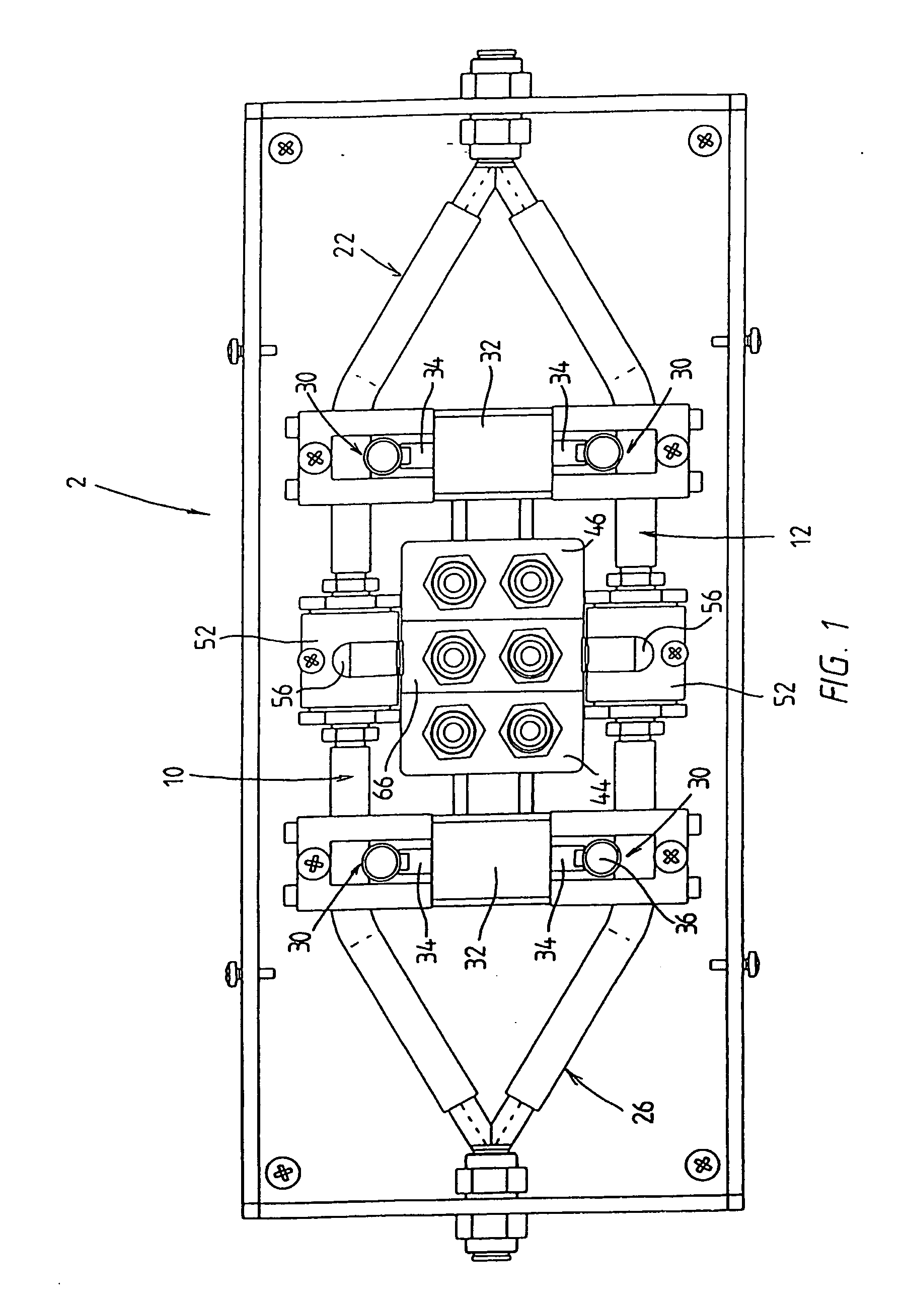
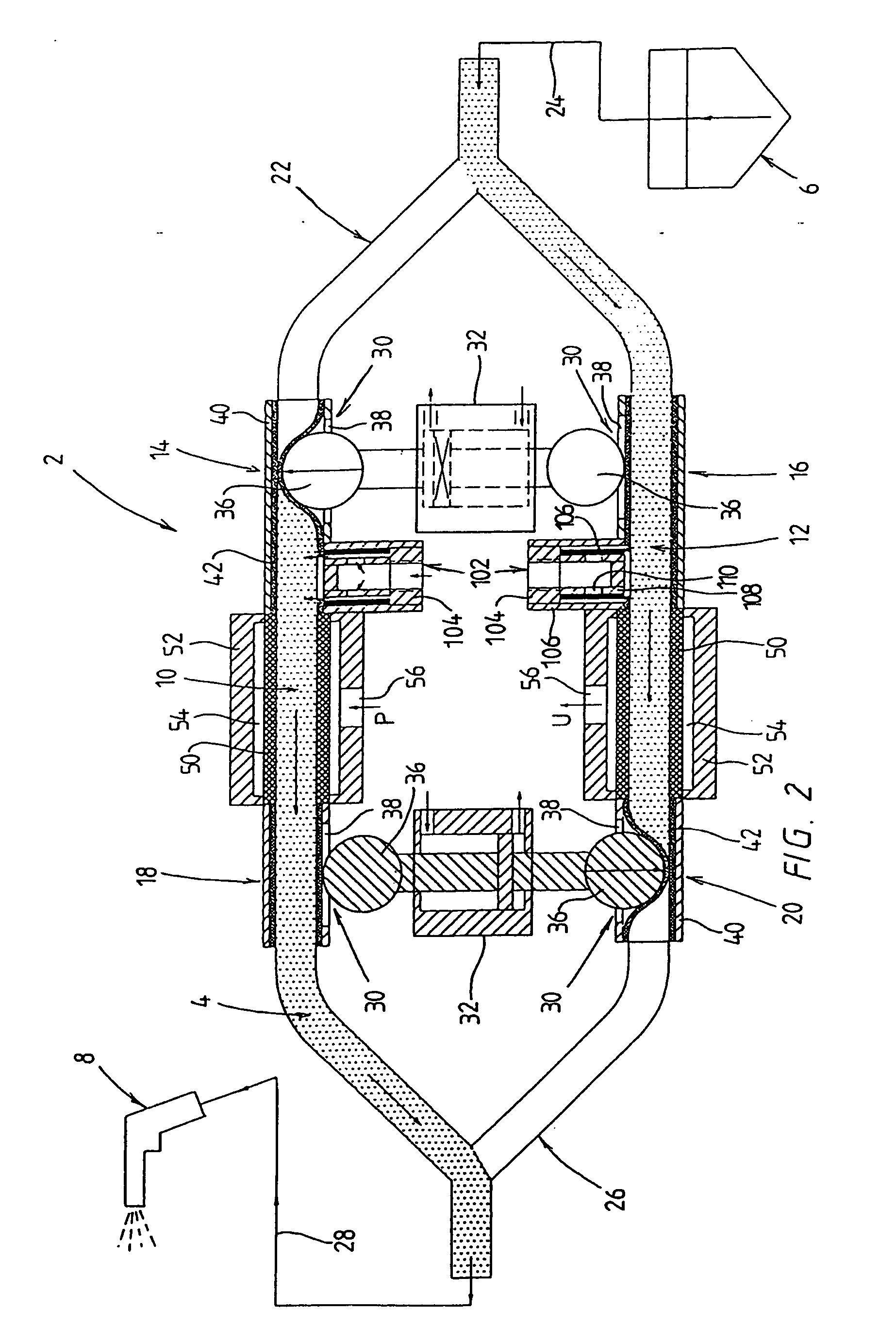
[0025] The device 2 shown in the drawings of FIGS. 1 and 2 is used for the pneumatic conveyance of powder coating material for the electrostatic powder coating of objects in a powder coating installation. The powdered coating material is conveyed in dense phase from a reservoir 6 to a spray gun 8. Alternatively, however, the device shown in FIGS. 1 and 2 can also be used in the extrusion of plastic or rubber tubes for the purpose of conveying powdered talc by means of compressed air from a reservoir to an extrusion die (not shown), through which the mixture of powdered talc and compressed air is fed into the inside of a tube that has just been extruded in order to coat the inside surface of the tube with the powdered talc to reduce friction.

[0026] As is shown best in FIG. 2, the device 2 has two parallel cylindrical metering chambers 10, 12, whose oppositely open ends form an inlet 14, 16 or an outlet 18, 20 for the powder coating material 4 that is being conveyed and are connected...


PUM


Abstract

The invention concerns a method and a device for monitoring flow conditions in a pipe system (28), into which a mixture of pulverulent material and compressed conveying air is admitted from a feed pump (2) by alternately filling at least two chambers (10, 12) of the feed pump (2) with pulverulent material and then alternately emptying the chambers into the pipe system (28) by feeding compressed conveying air from a compressed air source (48) into one of the previously filled chambers (10, 12). To detect fluctuations in the flow conditions and especially to detect obstructions within the pipe system (28) and in this way to allow continuous process monitoring, the invention proposes that the flow rate of the compressed conveying air be measured and analyzed in a common compressed air feed line (70) leading from the compressed air source (48) to the two chambers (10, 12).

Description

RELATED APPLICATIONS [0001] The present application claims priority to German Patent Application Number 102004052949.3, filed Oct. 29, 2004, which is fully incorporated by reference herein. BACKGROUND OF THE INVENTION [0002] The invention concerns a method and a device for monitoring flow conditions in a pipe system in accordance with the introductory clause of claims 1 and 9. [0003] So-called dense phase pumps are often used in powder coating installations to convey powder coating material by compressed air from a reservoir through a hose line to spray guns or other types of spray application devices, from which the coating material can then be sprayed onto the objects to be coated. [0004] A dense phase pump of this type for the conveyance of powder coating material is described, for example, in DE 102 47 829 A1 and DE 102 61 053 A1 of the present applicant. The previously known pump has two parallel metering chambers, one of which is subjected to a negative pressure to draw powder...

Claims


Application Information

Patent Timeline
IPC IPC(8): B65G51/08
CPCB05B7/1459B05B12/006B65G53/66
Inventor KLEINEIDAM, ULFKLEINEIDAM, ANDREAS
Owner NORDSON CORP
Learn More