
Time-resolved scanning patterns for intrastromal surgery

a scanning pattern and intrastromal technology, applied in the field of time-resolved scanning patterns for intrastromal surgery, can solve the problems of tearing (mechanical damage), scorching, and peripheral tissue of ablated tissue subject to adverse side effects, and decaying within a few nanoseconds, and causing shock wave, however

Active Publication Date: 2006-05-04
TECHNOLAS PERFECT VISION
View PDF27 Cites 23 Cited by
  • Summary
  • Abstract
  • Description
  • Claims
  • Application Information

AI Technical Summary

Problems solved by technology

For one, tissue that is peripheral to the ablated tissue is subject to adverse side effects, such as tearing (mechanical damage) and scorching (thermal damage).
The shock wave, however, decays within a few nanoseconds.

Method used


Image

  • Time-resolved scanning patterns for intrastromal surgery
  • Time-resolved scanning patterns for intrastromal surgery
  • Time-resolved scanning patterns for intrastromal surgery

Examples


Embodiment Construction

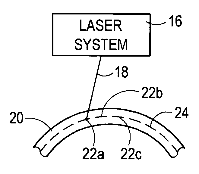
[0023] Referring to FIG. 3, an environment for the present invention is shown wherein a laser system 16 is used to focus a laser beam 18 into a transparent material 20, such as the stroma of an eye. As indicated, the laser beam 18 is focused to a succession of focal spots 22 in the transparent material 20, of which the focal spots 22a-c are only exemplary. Further, as also indicated in FIG. 3, the succession of focal spots 22 are maneuvered to create a pattern 24 within the material 20. For purposes of the present invention, the pattern 24 may be of any form or design well known in the pertinent art, such as a line, a curve, or a spiral.

[0024] Preferably, the focal spots 22 in pattern 24 are created by a laser beam 18 which includes a train of laser pulses that have a pulse repetition rate in the multi KHz region (i.e. around 10 KHz or more). Further, each pulse in the train preferably has the following characteristics: 1) a pulse length (duration) in a range of 1-1000 femtoseconds...


PUM


Abstract

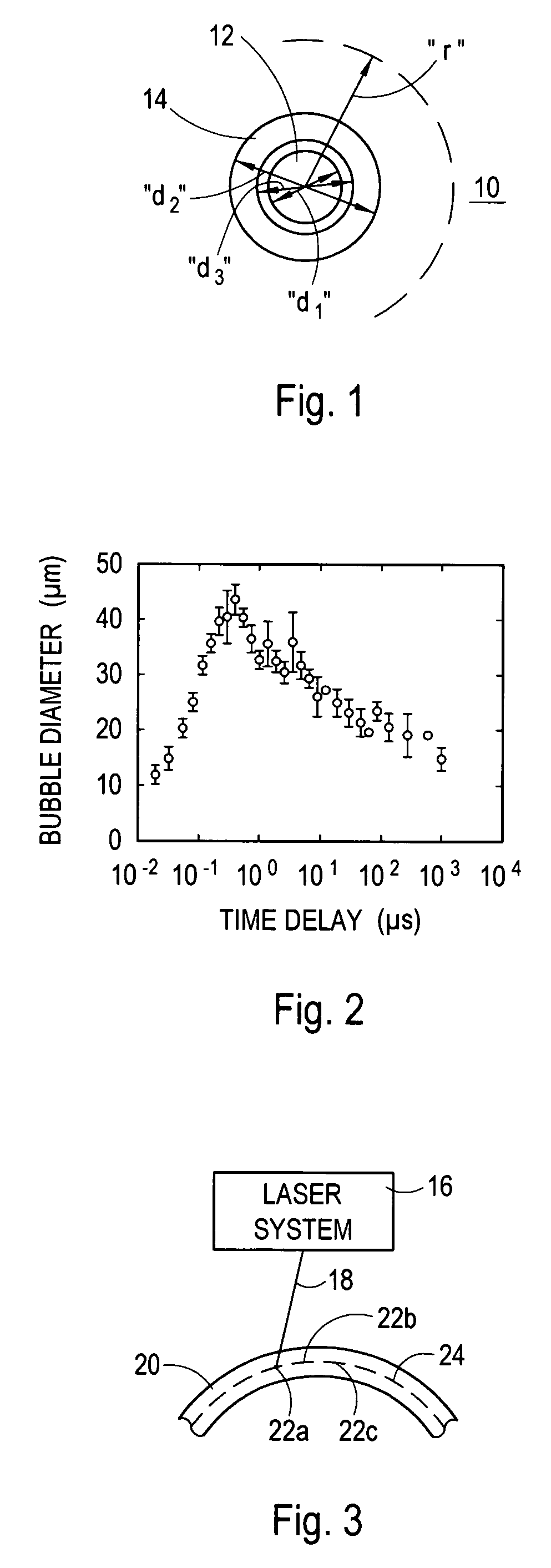
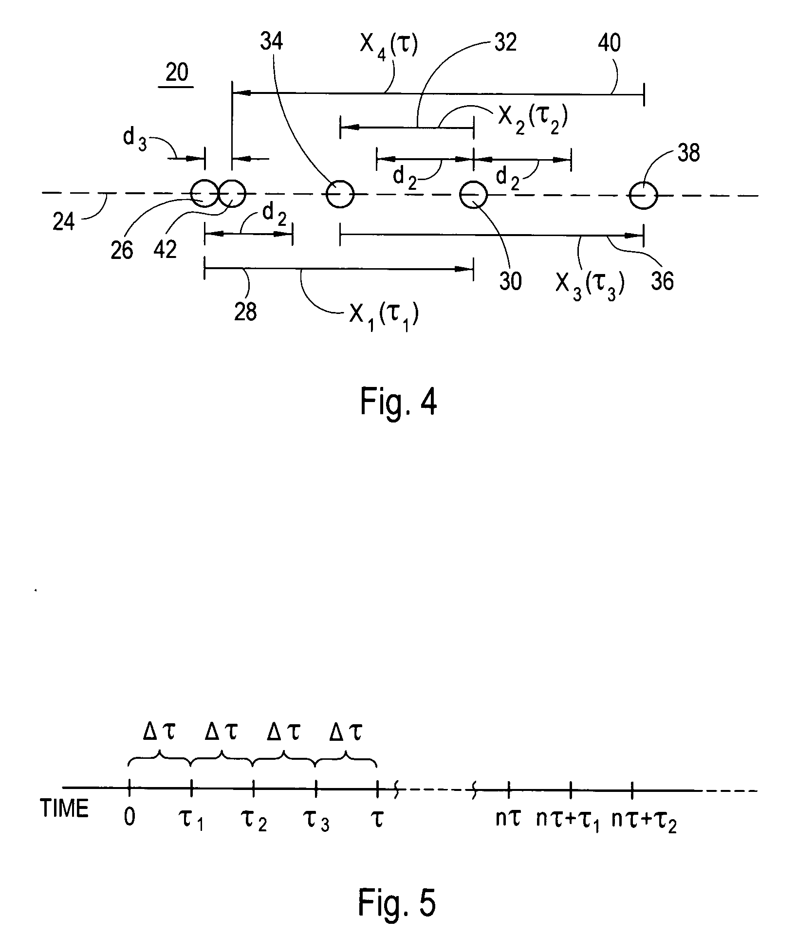
A system and method for performing laser induced optical breakdown (LIOB) in corneal tissue of an eye requires calculating a pattern of focal spots. LIOB is then induced at a first focal spot, and is continued at a plurality of interim focal spots within a time period τ. Each focal spot has a diameter “d1” and generates a temporal cavitation bubble of diameter “d2”. It then collapses within time “τ” to a substantially stationary diameter “d3”, with (d1≦d3≦d2). Importantly, each focal spot is located more than “d2” from every other interim focal spot within the time period of “τ”. At the time “τ”, a second focal spot in the pattern can be generated at a distance “d3” from the first focal spot. This process is then continued with another plurality of interim focal spots being generated within another time period “τ”.

Description

FIELD OF THE INVENTION [0001] The present invention pertains generally to systems and methods for creating spot patterns for ophthalmic refractive laser surgery. More particularly, the present invention pertains to systems and methods which minimize the residual effects from laser induced optical breakdown (LIOB) at earlier laser focal points, on LIOB at subsequent laser focal points. The present invention is particularly, but not exclusively, useful for systems and methods wherein LIOB at adjacent focal points in the stroma (transparent material) is performed in accordance with a predetermined spatial and temporal separation. BACKGROUND OF THE INVENTION [0002] During an ophthalmic laser surgical procedure, wherein stromal tissue within the cornea is ablated, the ablation is caused by an effect known as Laser Induced Optical Breakdown (LIOB). Typically, LIOB in the stroma is accomplished using pulsed laser beams that may have pulse repetition rates as high as 10 KHz. In detail, the ...

Claims


Application Information

Patent Timeline
Patent Type & Authority Applications(United States)
IPC IPC(8): A61F9/008A61B18/18
CPCA61F9/008A61F9/00825A61F2009/00872A61F2009/00897
Inventor LOESEL, FRIEDERKUHN, TOBIAS
Owner TECHNOLAS PERFECT VISION
Learn More