Method for creating, trapping and manipulating a gas bubble in liquid

A liquid and micro-bubble technology, applied in the field of optical capture, can solve the problems of surrounding target damage and limited application

Inactive Publication Date: 2011-05-18
CARL ZEISS SMS GMBH
View PDF5 Cites 8 Cited by
  • Summary
  • Abstract
  • Description
  • Claims
  • Application Information

AI Technical Summary

Problems solved by technology

The use of high average laser power above 210mW and the generation of white light can cause damage to surrounding targets, which will greatly limit its applications, e.g. in medicine and biology

Method used


Image

  • Method for creating, trapping and manipulating a gas bubble in liquid
  • Method for creating, trapping and manipulating a gas bubble in liquid
  • Method for creating, trapping and manipulating a gas bubble in liquid

Examples


Embodiment 1

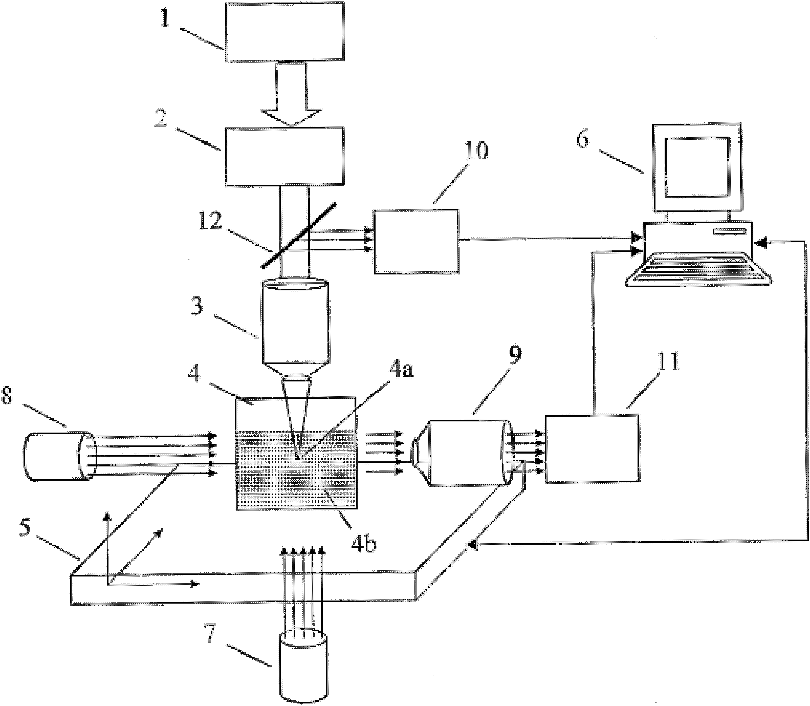
[0060] A laser pulse with a width of 200 fs and a wavelength of 800 nm (1, such as figure 1 ) directly through the variable attenuator (2) and focused into distilled water through a dry objective lens with a numerical aperture of 0.55. Controlled by a computer (6), the glass tube (4) filled with water (4b) is moved relative to the focal point (4a) of the objective lens using a three-axis open-frame displacement system (5). The device has two vision systems, one along and one perpendicular to the laser beam. Each vision system has an illumination source (7, 8), an objective lens (3, 9) and a CCD camera (10, 11). Observation along the laser beam is carried out through the same objective lens (NA=0.55, compensation depth 6.3 mm) when the breakdown laser radiation is initiated using the beam splitter (12). The vision system perpendicular to the laser beam uses an objective lens (9) with a numerical aperture of 0.3.

[0061] As mentioned above, after a breakdown in water typical...

Embodiment 2

[0064] A 200 fs laser pulse of a Ti-sapphire laser with a pulse energy of 150 nJ and a repetition rate of 100 kHz was focused into water through an immersion objective lens of 0.75 NA. In this case, stably trapped air bubbles can be observed at any depth of the focal point of the objective lens in water. Trapped air bubbles can be moved in the water by changing the angle of incidence of the laser beam on the focusing objective or by moving the focus in a transverse direction along the beam axis relative to the water container.

Embodiment 3

[0066] The 50 fs laser pulse of the Ti-sapphire oscillator with a pulse energy of 100 nJ and a repetition rate of 5 MHz was focused into water through an immersion objective lens of 0.75 NA. In this case, stably trapped air bubbles can be observed in water at any depth of the focal point of the objective. Trapped air bubbles can be moved in the water by changing the angle of incidence of the laser beam on the focusing objective or by moving the focus in a transverse direction along the beam axis relative to the water container.


PUM

PropertyMeasurementUnit
diameteraaaaaaaaaa

Abstract

A method for producing, trapping and manipulating a gas microbubble in liquid is disclosed. The method includes providing a pulsed laser source for generating a pulsed laser radiation and focusing optics; and focusing a pulsed laser radiation to a focal zone within the liquid, with energy exceeding the threshold of optical breakdown in the liquid at the focal zone. It is also suggested to use focusing optics to focus the laser beam to a focal point at a depth close to the compensation depth of the focusing optics for spherical aberration.

Description

technical field [0001] The present invention relates to optical trapping, and more particularly to a method of making, trapping and controlling gas bubbles in liquids. Background technique [0002] Trapping and controlling particles is of great importance in nanotechnology and microscopy, as well as in medical and biological applications. Trapping and manipulating particles typically involves applying optical pressure to the particles in a liquid using optical traps (optical or laser tweezers). Although the force of optical tweezers is small, it is sufficient in some cases for the non-contact capture and manipulation of cells and other particles. [0003] An illustration of the feasibility of nondestructively trapping and moving particles using optical tweezers is provided in the reference [Acceleration and trapping of particles by radiation pressure", Phys. Rev. Lett. 24(4), 156-159 (1970)]. Since then, the design of optical tweezers has been continuously improved.Many im...

Claims


Application Information

Patent Timeline
Patent Type & Authority Applications(China)
IPC IPC(8): G01N21/01
CPCA61B18/26G02B21/32A61B2018/263
Inventor 谢尔盖·澳斯姆柯夫列夫·德沃尔金弗拉基米尔·德米特里耶夫
Owner CARL ZEISS SMS GMBH
Why Eureka
Try Eureka