System and method for altering internal stress distributions to reshape a material

a stress distribution and internal stress technology, applied in laser surgery, medical science, surgery, etc., can solve problems such as irregularities and optical aberrations

Active Publication Date: 2009-10-22
TECHNOLAS PERFECT VISION
View PDF11 Cites 7 Cited by
  • Summary
  • Abstract
  • Description
  • Claims
  • Application Information

AI Technical Summary

Benefits of technology

[0009]For the present invention, a laser unit is used to cut material (stromal tissue) on the boundary (interface) surface of the underlying volume. The extent and scope of this cut will be determined by the extent and scope of the deviation that is used to identify the underlying volume. As for the shape of the cut, depending on the particular reconfiguration that is desired, the cut may be a planar cut or a cylindrical cut. The cut may also be otherwise customized for the particular requirements of the procedure. For example, a predictive model as disclosed in U.S. application Ser. No. 12 / 016,857 for an invention entitled “Finite Element Modeling of the Cornea,” which is assigned to the same assignee as the present invention, can be used for this purpose. In any event, as noted above, the cuts are intended to disrupt the stress distribution on the boundary (interface) surface between material in the underlying volume and adjacent material. More specifically, the cuts may be made on only portions of a tissue volume boundary and may be made on the boundaries of more than one volume. The consequence is that the external force (e.g. intraocular pressure “IOP”) will then alter the configuration of the transparent material in response to the weakening of the material that has been cut.

Problems solved by technology

Moreover, these irregularities persist under the influence of biomechanical forces that develop mostly in the stroma.
When irregularities are present, however, the consequences are the creation of optical aberrations.

Method used


Image

  • System and method for altering internal stress distributions to reshape a material
  • System and method for altering internal stress distributions to reshape a material
  • System and method for altering internal stress distributions to reshape a material

Examples


Embodiment Construction

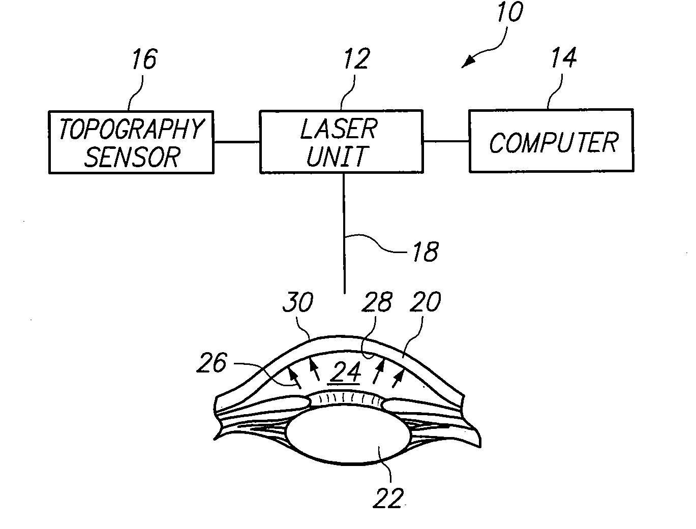
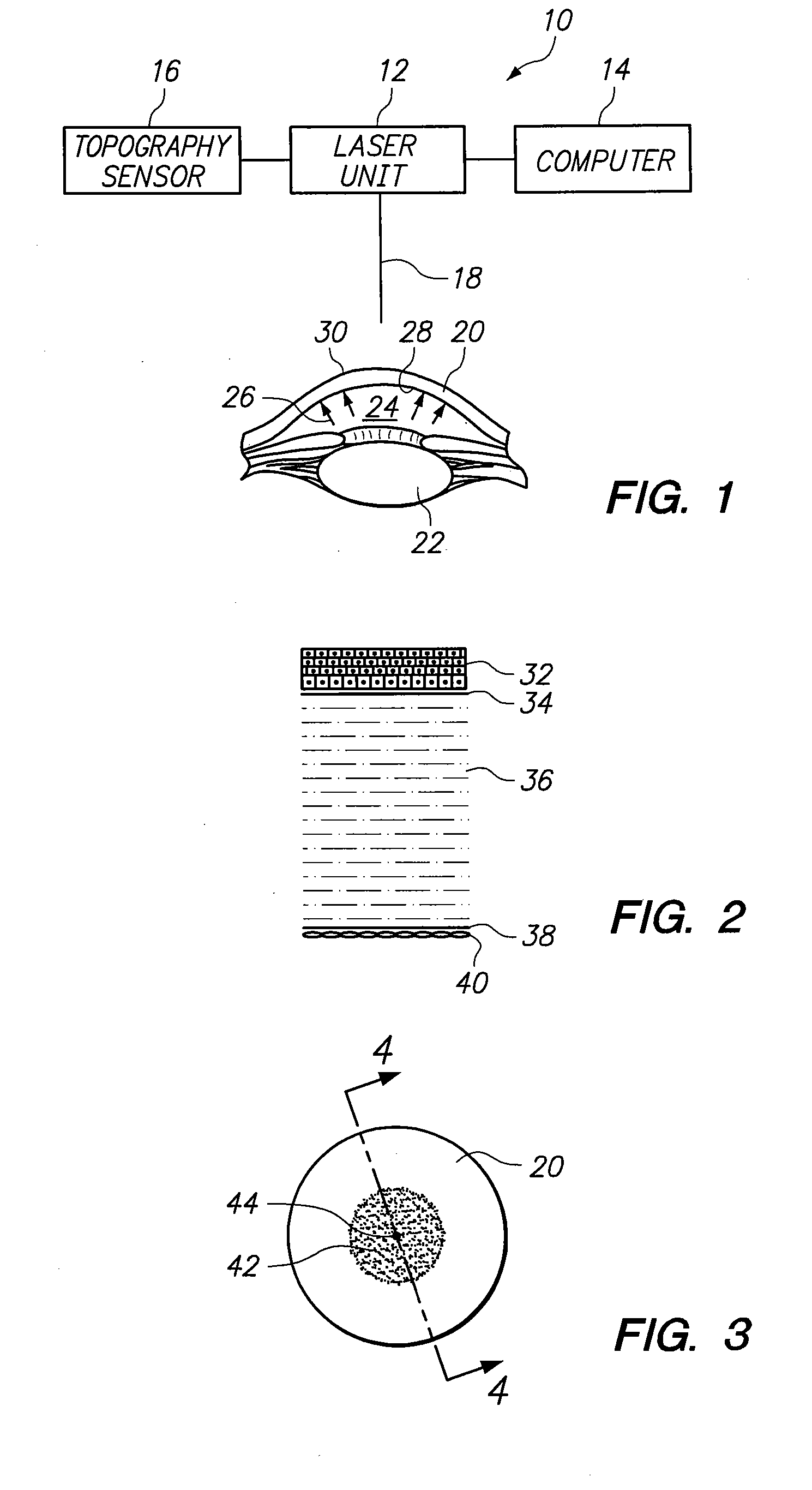
[0018]Referring initially to FIG. 1, a system in accordance with the present invention is shown and is generally designated 10. As indicated and shown, the system 10 includes a laser unit 12, that is electronically connected to a computer 14, and to a topography sensor 16. For purposes of the present invention, the laser unit 12 is preferably of a type that can generate a laser beam 18 that is characterized by femtosecond pulses. Importantly, the laser beam 18 needs to be capable of altering transparent material, such as the cornea 20 of an eye, by a process known as Laser Induced Optical Breakdown (LIOB). Further, the topography sensor 16 can be a corneal topographer of any type well known in the pertinent art, that is capable of detecting aberrations in the cornea 20.

[0019]Still referring to FIG. 1, the anatomy of the anterior portion of an eye is shown to include the cornea 20 and a lens 22. The aqueous humor 24 is a clear fluid filing the space between the lens 22 and the cornea...


PUM


Abstract

A system and method for altering the configuration of a transparent material (e.g. the cornea of an eye) requires identifying local stress distribution patterns inside the material. These patterns are then used to define boundary (interface) surfaces between volumes within the material. In operation, a laser unit performs Laser Induced Optical Breakdown (LIOB) along selected boundary surfaces to disrupt stress distribution patterns between volumes of the material that are separated from each other by the boundary surface. This LIOB allows an externally applied force to thereby alter the configuration of the material.

Description

FIELD OF THE INVENTION[0001]The present invention pertains generally to systems and methods for performing ophthalmic laser surgery. More particularly, the present invention pertains to laser systems that weaken corneal tissue over selected surfaces inside the cornea. The present invention is particularly, but not exclusively, useful as a system and method for weakening corneal tissue on selected boundary surfaces between tissue volumes, where the surfaces have been identified by abnormal deviations in stress distributions.BACKGROUND OF THE INVENTION[0002]From a mechanical perspective, the cornea of an eye includes a Bowman's membrane that has exceptionally good tensile strength. Anatomically, Bowman's membrane is a relatively thin layer of tissue that is located just under the epithelium on the anterior surface of the cornea. More specifically, Bowman's membrane extends across the cornea, and its peripheral edge connects with the sclera. Most corneal tissue, however, is not in Bowm...

Claims


Application Information

Patent Timeline
Patent Type & Authority Applications(United States)
IPC IPC(8): A61F9/008
CPCA61F9/008A61F2009/00882A61F2009/00872A61F9/00827
Inventor LOESEL, FRIEDERBILLE, JOSEF F.
Owner TECHNOLAS PERFECT VISION
Why Eureka
Try Eureka