Chamfering method for brittle substrate

A brittle material substrate and chamfering technology, applied in stone processing equipment, stone processing tools, fine working devices, etc., can solve the problems of chamfering surface depression, control, and difficult chamfering surface shape

Inactive Publication Date: 2009-03-18
MITSUBOSHI DIAMOND IND CO LTD
View PDF5 Cites 39 Cited by
  • Summary
  • Abstract
  • Description
  • Claims
  • Application Information

AI Technical Summary

Problems solved by technology

[0023] However, using the previous CO 2 The chamfered surface 54 formed by the laser scribing of the laser will form a depression anyway
Even if the irradiation direct

Method used


Image

  • Chamfering method for brittle substrate
  • Chamfering method for brittle substrate
  • Chamfering method for brittle substrate

Examples


Embodiment Construction

[0057] Embodiments of the present invention will be described below using the drawings. In addition, this invention is not limited to embodiment demonstrated below, Various aspects are included in the range which does not deviate from the summary of this invention.

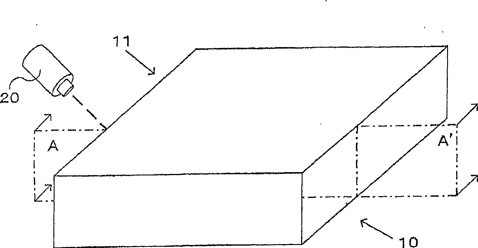
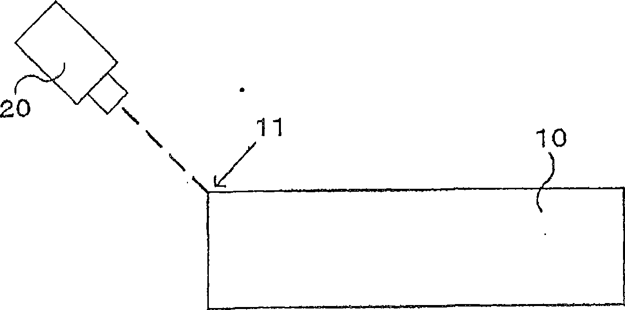
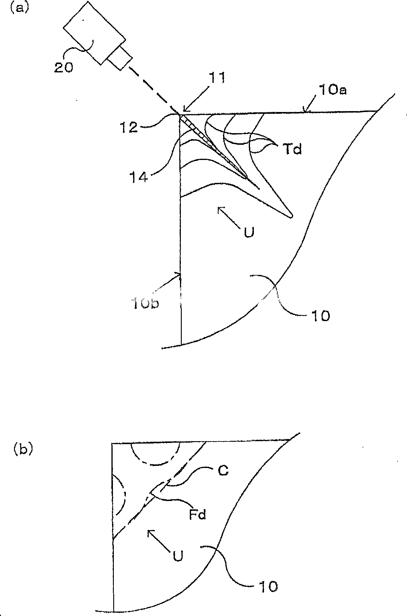
[0058] figure 1 It is a figure which shows the chamfering processing method of the brittle material substrate which is one embodiment of this invention. figure 2 is shown along the figure 1 The A-A' section diagram. An Er:YAG laser light source 20 (hereinafter referred to as Er laser light source 20) is arranged at a position opposite to the edge line 11 of the glass substrate 10 to be chamfered, and the laser light is inclined from the edge line 11 of the substrate toward the inside of the substrate. incident. Then, the glass substrate 10 is relatively moved with respect to the laser light source 20 , and the laser light is scanned along the edge line 11 . Specifically, scanning is performed by operating ...


PUM


Abstract

The invention provides a chamfering method for brittle material substrate, which can form small depression for chamfering processing surface. A thermal stress distribution field which can control cracks in the substrate is formed by using a laser source with absorptivity of 0.05 to 0.95 relative to the substrate (10), irradiating laser near a edge line (11), forming temperature distribution in the substrate through a laser absorption region (14) from the edge line to inner part of the substrate, extending the cracks through thermal stress distribution in the substrate generated by the temperature distribution, and adjusting extension direction of the cracks.

Description

technical field [0001] The present invention relates to a chamfering method of an edge line (ridge line) formed on an end surface of a brittle material substrate, and more specifically relates to reducing the depression of the chamfered surface formed along the edge line, and more preferably making it flat The chamfering method of the machined surface. Background technique [0002] Brittle material substrates such as glass substrates are used in various products by being processed into desired sizes and shapes. Generally, brittle material substrates are processed by existing processing technologies such as dicing, grinding wheel scribing, and laser scribing. However, the edge lines of the end faces of the substrates divided by these processing technologies are very sharp, and chips are generated when only a small impact is applied. or micro-cracks and other adverse conditions. For example, in a glass substrate for a flat panel display (FPD), chips generated due to chipped ...

Claims


Application Information

Patent Timeline
IPC IPC(8): C03B33/02B23K26/00B23K26/40B28D1/24B28D5/00C03B33/09
CPCC03B33/0222C03B33/027C03B33/091C03B33/102Y02P40/57
Inventor 清水政二
Owner MITSUBOSHI DIAMOND IND CO LTD
Why Eureka
Try Eureka