Steel frame stress reduction connection

a steel frame and stress reduction technology, applied in the direction of pillars, cranes, building components, etc., can solve the problems of life loss, complex assessment, collapse of structure, etc., and achieve the effect of reducing the maximum magnitude and uniform distribution

Inactive Publication Date: 2006-05-23
SEISMIC STRUCTURAL DESIGN ASSOCS
View PDF30 Cites 37 Cited by
  • Summary
  • Abstract
  • Description
  • Claims
  • Application Information

AI Technical Summary

Benefits of technology

[0006]The general object of the present invention is to provide new and improved beam to column connections that reduce stress and / or strain caused by both static and dynamic loading. The improved connection of the present invention extends the useful life of the steel frames of new buildings, as well as that of steel frames in existing buildings when incorporated into a retrofit modification made to existing buildings.
[0007]A further object is to provide an improved beam to column connection in a manner which generally, evenly distributes static or dynamic loading, and stresses, across the connection so as to minimize high stress concentrations along the connection.
[0008]Another object of the present invention is to reduce a dynamic loading stress applied between the beam and the column flange connection of a steel frame structure.

Problems solved by technology

These assessments are compounded in complexity when considering loads for seismic events, and determining the stresses and strains caused by these loads in structures are compounded in areas where earthquakes occur.
Under the high loading and stress conditions from a large earthquake, or from repeated exposure to milder earthquakes, the connections between the beams and columns can fail, possibly resulting in the collapse of the structure and the loss of life.
While suitable for use under normal occupational loads and stresses, often these connections have not been able to withstand greater loads and stresses experienced during an earthquake.
Even if the connections survive an earthquake, that is, don't fail, changes in the physical properties of the connections in a steel frame may be severe enough to require structural repairs before the building is fit for continued occupation.

Method used


Image

  • Steel frame stress reduction connection
  • Steel frame stress reduction connection
  • Steel frame stress reduction connection

Examples


Embodiment Construction

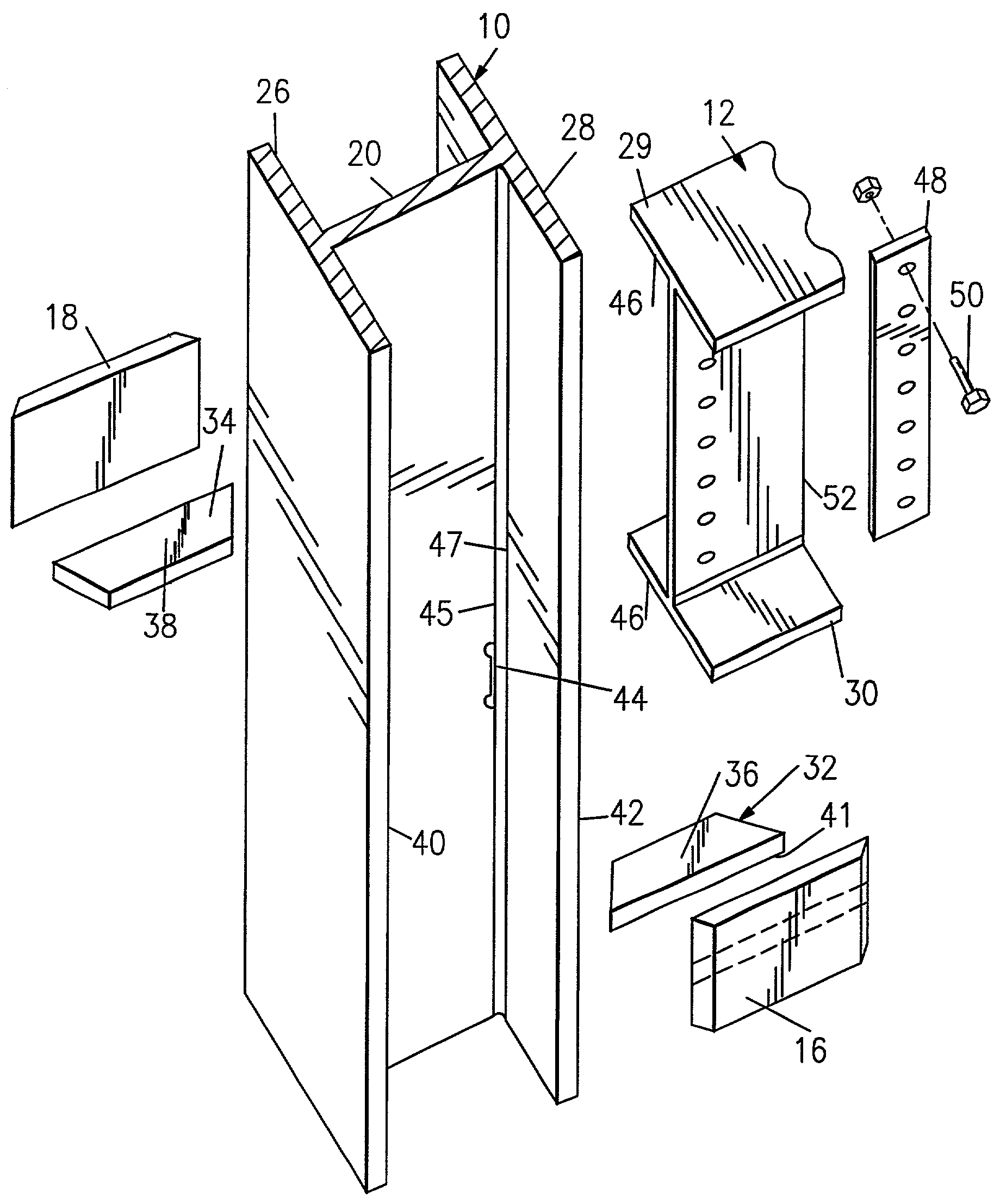
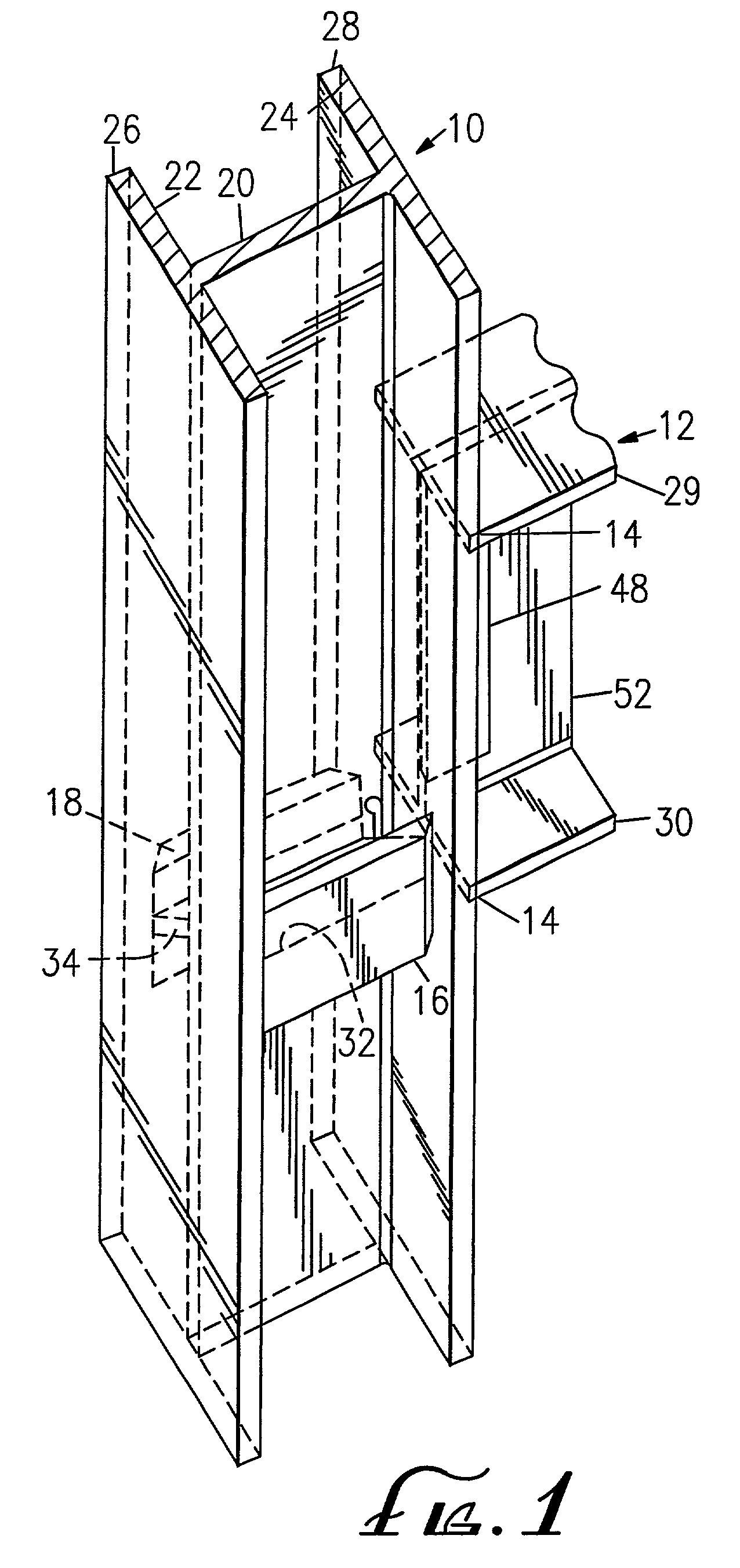
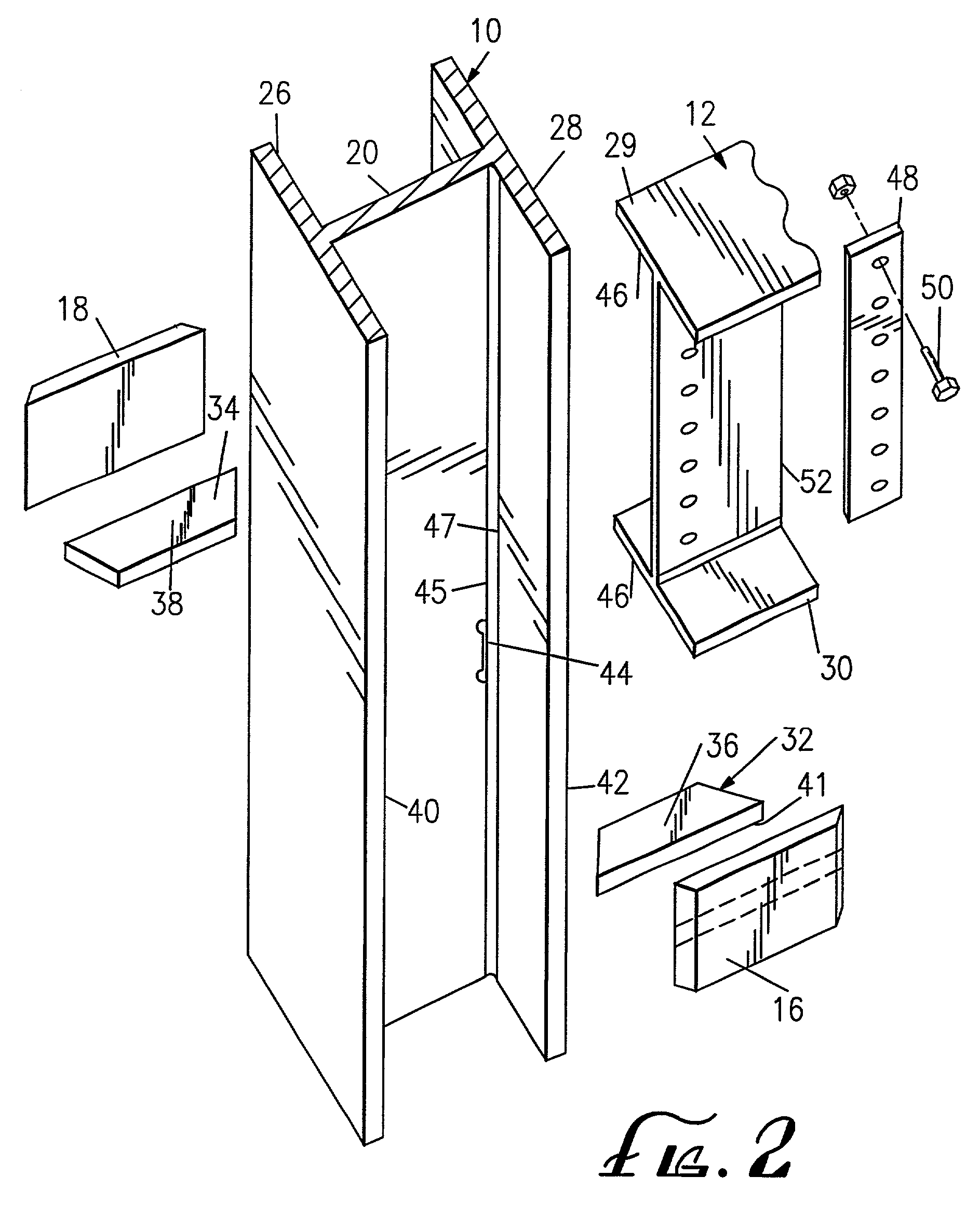
[0060]Referring to the Figures, especially 1–4, 9–15, and 22–23, the skeleton steel frame used for seismic structural support in the construction of buildings in general frequently comprises a rigid or moment, steel framework of columns and beams connected at a connection. The connection of the beams to the columns may be accomplished by any conventional technique such as bolting, electric arc welding or by a combination of bolting and electric arc welding techniques.

[0061]Referring to FIGS. 22 and 23, a conventional W 14×176 (360×262) column 282 and a W 27×94 (690×140) beam 284 are conventionally joined by shear plate 286 and bolts 288 and welded at the flanges. The parenthetical notation is the beam or column size expressed in metric units. The column 282 includes bolt shear plate 286 welded at a lengthwise edge along the lengthwise face of the column flange 290. The shear plate 286 is made to be disposed against opposite faces of the beam web 292 between the upper and lower flang...


PUM


Abstract

The present invention provides for improvement of ductility and strength performance of connections in structural steel buildings made typically with rolled structural shapes, specifically in bolted and / or welded beam-to-column connections with welded flanges, by greatly reducing the very significant uneven stress distribution found in the conventionally designed connection at the column / beam weld, through use of slots in column and / or beam webs with or without continuity plates in the area of the column between the column flanges, as well as, optionally, extended shear plate connections with additional columns of bolts for the purpose of reducing the stress concentration factor in the center of the flange welds. Moreover, the slots in beam web adjacent to the beam flanges allow the beam web and flange to buckle independently thereby eliminating the degrading of the beam strength caused by lateral-torsional bucking.

Description

[0001]This is a continuation-in-part of application Ser. No. 08 / 957,516 filed Oct. 24, 1997 now U.S. Pat. No. 6,237,303 which is a continuation-in-part of Application Ser. No. 08 / 522,740 filed Sep. 1, 1995, now U.S. Pat. No. 5,680,738, which is a continuation-in-part of application Ser. No. 08 / 419,671, filed Apr. 11, 1995, now abandoned.FIELD OF THE INVENTION[0002]The present invention relates broadly to load bearing and moment frame connections. More specifically, the present invention relates to connections formed between beams and / or columns, with particular use, but not necessarily exclusive use, in steel frames for buildings, in new construction as well as modification to existing structures.BACKGROUND[0003]In the construction of modern structures such as buildings and bridges, moment frame steel girders and columns are arranged and fastened together, using known engineering principles and practices to form the skeletal backbone of the structure. The arrangement of the girders,...

Claims


Application Information

Patent Timeline
Patent Type & Authority Patents(United States)
IPC IPC(8): E04C3/32E04B1/24
CPCE04B1/2403E04B2001/2415E04B2001/2448E04B2001/2445E04B2001/2442
Inventor ALLEN, CLAYTON J.PARTRIDGE, JAMES E.RICHARD, RALPH M.
Owner SEISMIC STRUCTURAL DESIGN ASSOCS
Why Eureka
Try Eureka