Adjustable instrumentation for spinal implant insertion

a technology of spinal implants and adjustable instruments, applied in the field of spinal intervertebral fusion implant insertion instruments, can solve the problems of requiring separate costly instruments for each different surgical function, affecting the use of each instrument for a given approach, and affecting the effect of the operation

Inactive Publication Date: 2006-05-04
WARSAW ORTHOPEDIC INC
View PDF99 Cites 78 Cited by
  • Summary
  • Abstract
  • Description
  • Claims
  • Application Information

AI Technical Summary

Benefits of technology

[0054] In a further aspect, the at least two different heads are selected from the group consisting of any two different head configurations, the configurations forming categories, each category having one or more different configurations, the categories including a chisel, an implant gripping head, an implant impacting head, an implant inserter, a rasp, a distractor, a trial, a curette and a rongeur.

Problems solved by technology

However, the problem with the suggested techniques and instrumentation of the prior art as discussed above is that separate costly instruments are required for each different surgical function.
These instruments are costly.
In addition, each instrument has limited use for a given approach and is difficult to use for other different approaches.
In addition, the surgeon using a fixed angled instrument possibly would have difficulty in some situations displacing the instrument in a relatively narrow space.

Method used


Image

  • Adjustable instrumentation for spinal implant insertion
  • Adjustable instrumentation for spinal implant insertion
  • Adjustable instrumentation for spinal implant insertion

Examples


Embodiment Construction

)

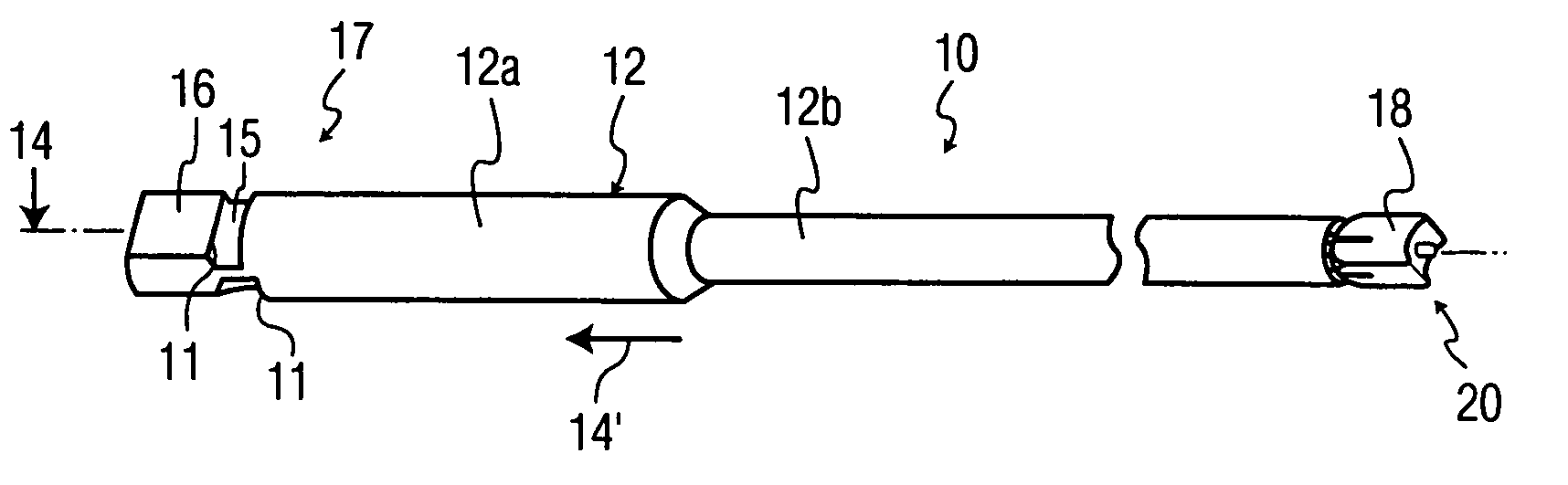
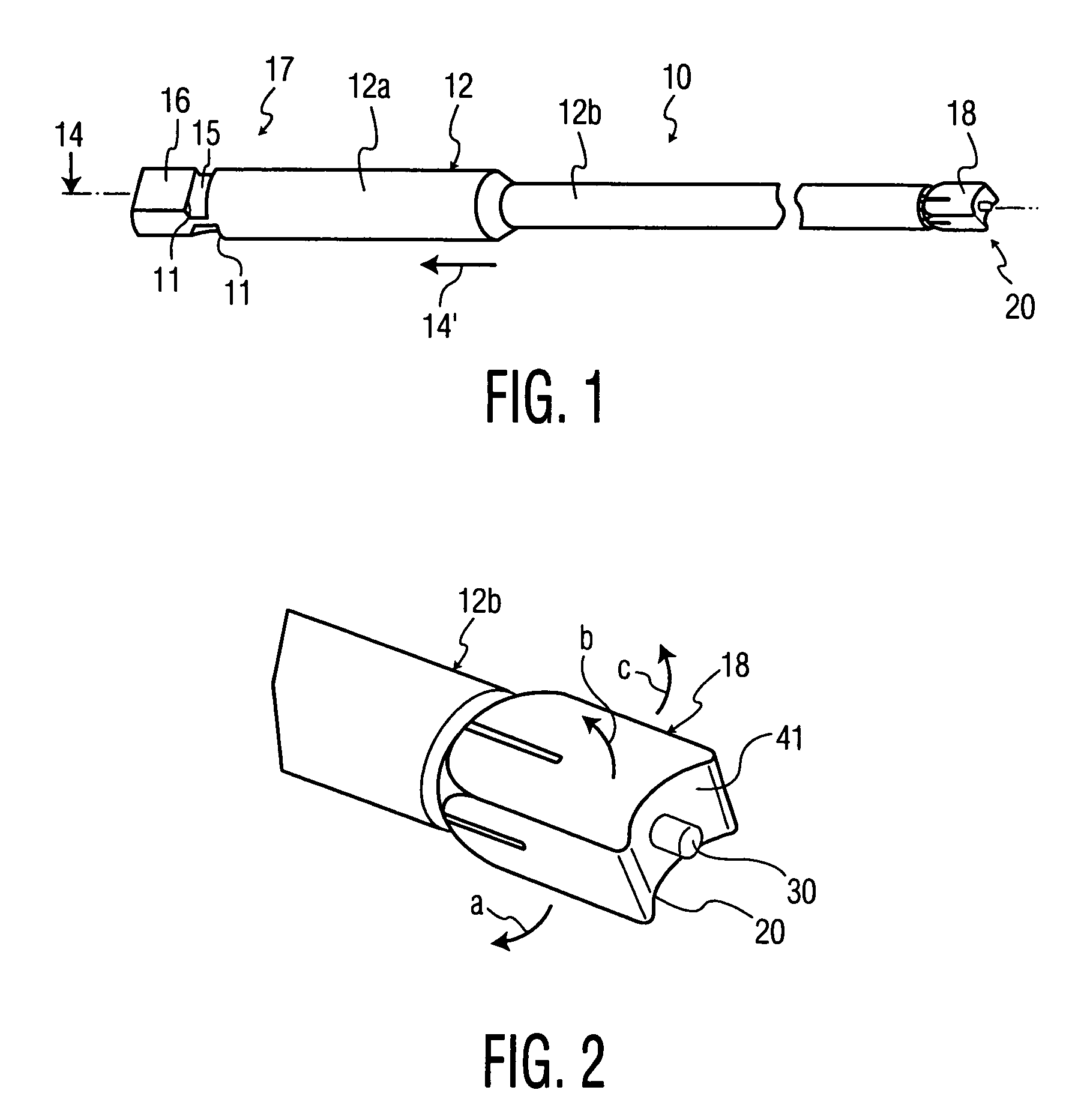
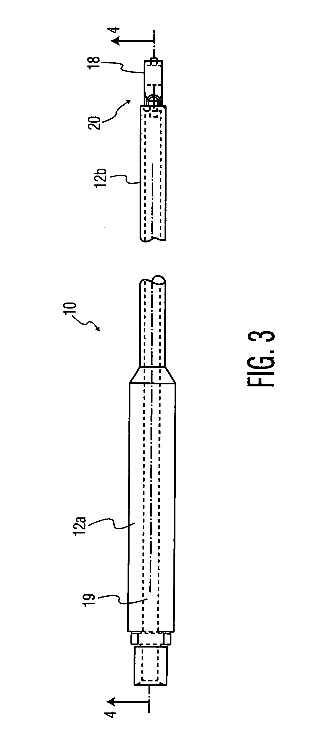
[0130] In FIG. 1, surgical instrument 10 comprises an elongated body 12 having a longitudinal axis 14, and a handle extension 16 attached to a cylindrical handle segment 12a of the body 12 at a proximal end 17 of the instrument 10. An implant manipulating and engaging head 18 is attached to a cylindrical shaft segment 12b of the body 12 at a distal end 20 of the instrument 10. The body 12 defines a hollow cavity 24 as shown in FIG. 8. The handle extension 16 and the handle segment 12a define a slot 11 (shown in FIG. 6) therebetween for receiving a knob 15. The knob 15 may be threaded to a mating threaded portion 19′ of a shank 19, as shown in FIG. 4. The threaded portion 19′ has a smaller diameter than the non-threaded portion of the shank 19. The knob 15 is rotatably threaded to the threaded portion 19′ (shown in FIGS. 3 and 4) via a threaded central opening 13 in the knob 15 (shown in FIG. 5). The shank 19 is positioned in the interior 9 of the body 12 and extends through the bod...


PUM


Abstract

A plurality of differently configured bone spinal implants for insertion in a spine have a cylindrical bore for receiving an insertion head stud. A plurality of instruments are disclosed each of which have a first connection element which is either a male or female member such as e.g., a ball and socket, a cylinder and socket and so on for forming either a stationary or articulating interchangeable joint for a plurality of disc processing heads or implant insertion heads. The plurality of disc space processing heads or implant insertion heads have a complementary second joint member for interchangeable attachment to the first connection element. The implant insertion heads or disc processing heads have different configurations for different shaped implants. Different instrument insertion or disc processing heads such as implant inserters, impactors, rasps, distractors, curettes, rongeur, and so on are disclosed as being interchangeable with a common instrument in which articulating or fixed joints are provided the interchangeable heads.

Description

CROSS REFERENCE TO RELATED APPLICATIONS AND PATENTS [0001] Of interest are commonly owned copending provisional application Ser. No. 60 / 340,734 filed Oct. 30, 2001 and Ser. No. 60 / 372,972 filed Apr. 16, 2002, both in the name of John Winterbottom et al., both applications corresponding to U.S. utility application Ser. No. 10 / 282,552 filed Oct. 29, 2002 entitled Bone Implant and Insertion Tools and PCT application Serial No. PCT / US02 / 34466 filed Oct. 28, 2002, Ser. No. 10 / 086,041 entitled Spinal Intervertebral Implant Insertion Tool filed Oct. 25, 2001 in the name of Erik Martz et al. and Ser. No. 10 / 046,866 (now US Pub. No. US 2002 / 0058950 A1) entitled Implant Insertion Tool filed Jan. 15, 2002 in the name of John M. Winterbottom et al., Ser. No. 60 / 425,941 filed Nov. 13, 2002 in the name of Jo Wen Lin entitled Spinal Implant Insertion Adjustment Instrument and Implants for use Therewith and Ser. No. 09 / 705,377 entitled Spinal intervertebral Implant filed Nov. 3, 2000 in the name of...

Claims


Application Information

Patent Timeline
Patent Type & Authority Applications(United States)
IPC IPC(8): A61B17/58
CPCA61B17/1604A61B17/1606A61B17/1659A61B17/1671A61B17/320016A61B19/26A61B2017/00261A61B2017/00464A61B2017/0256A61B2017/2904A61B2017/2931A61F2/442A61F2/4455A61F2/4611A61F2002/30538A61F2002/30795A61F2002/4624A61F2002/4627A61F2002/4628A61F2002/4629A61F2002/4679A61F2250/0006A61B90/50A61F2/46A61F2/4603
Inventor MARTZ, ERIK O.LIN, JO-WENCHOW, DAVIDROSENTHAL, DANIEL
Owner WARSAW ORTHOPEDIC INC
Why Eureka
Try Eureka