Side branch stent graft

Active Publication Date: 2006-05-04
COOK MEDICAL TECH LLC
View PDF14 Cites 106 Cited by
  • Summary
  • Abstract
  • Description
  • Claims
  • Application Information

AI Technical Summary

Benefits of technology

[0016] It will be seen that by this invention there is provided a main flow lumen whose circumference increases from that of the main flow tube or stent graft to that of the sum of the main flow tube plus the side arm tube

Problems solved by technology

Often such damaged regions include side branch vessels.
There can be a problem with such side branch stent grafts that in the region of the bifurcation or exit of a side branch from a main tube, disruption to blood flow can

Method used


Image

  • Side branch stent graft
  • Side branch stent graft
  • Side branch stent graft

Examples


Embodiment Construction

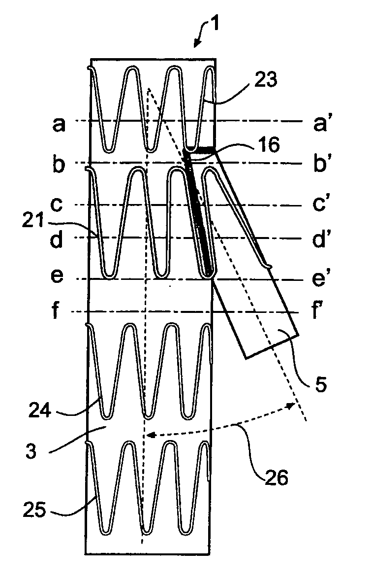
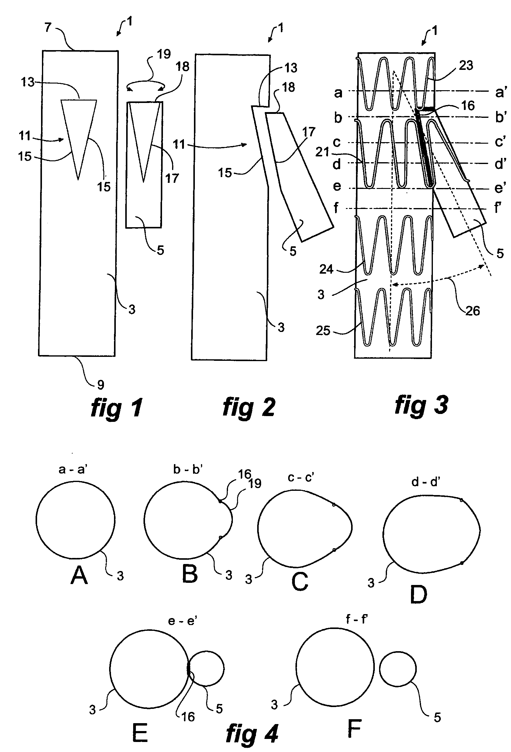
[0033] Now looking at the drawings and more particularly the first embodiment shown in FIGS. 1 to 4 it will be seen that the stent graft 1, according to one embodiment of the present invention, comprises a biocompatible graft material main tube 3 and a side arm 5 also comprises a biocompatible graft material.

[0034] For the purpose of assisting in the explanation of the present invention the stent graft main tube 3 has a proximal end 7 and a distal end 9 and blood flow would normally be from the proximal end 7 to the distal end 9.

[0035] To join the branch tube 5 to the main tube 3, according to one embodiment of the invention, a triangular aperture or fenestration generally shown as 11 is cut into the main tube 3. The triangular aperture or fenestration 11 is in the shape of an isosceles triangle with the base 13 at the proximal end and the substantially equal length sides 15 more distal. The side arm 5 has a bevel cut in it at one of its ends such that the remainder 18 of the circ...


PUM


Abstract

A joining arrangement between a main tube ( 3 ) and a side arm ( 5 ) in a side arm stent graft ( 1 ). The side arm ( 5 ) is stitched into an aperture ( 11 ) in the main tube and is in fluid communication with it. The aperture is triangular, elliptical or rectangular and the side arm is cut off at an angle to leave an end portion having a circumferential length equal to the circumference of the aperture. The side arm can also include a connection socket ( 76 ) comprising a first resilient ring ( 79 ) around the arm at its end, a second resilient ring ( 80 ) spaced apart along the arm from the first ring and a zig zag resilient stent ( 82 ) between the first and second rings. The zig-zag resilient stent can be a compression stent. Both the main tube and the side arm are formed from seamless tubular biocompatible graft material.

Description

CROSS-REFERENCE TO RELATED APPLICATIONS [0001] This application claims priority of provisional application Ser. No. 60 / 611,774, filed Sep. 21, 2004.TECHNICAL FIELD [0002] This invention relates to a stent graft used to restore the patency of a body lumen and in particular relates to a side branch or side arm stent graft. BACKGROUND OF THE INVENTION [0003] Where damage has occurred to an internal vessel of the human or animal body such as a blood vessel either by disease or by trauma it is possible to introduce to the blood vessel a stent graft by endoluminal techniques which will restore patency of the blood vessel across the damaged region. Often such damaged regions include side branch vessels. To ensure the blood flow can go into the side branch vessel side branch stent grafts are used. [0004] There can be a problem with such side branch stent grafts that in the region of the bifurcation or exit of a side branch from a main tube, disruption to blood flow can occur. This may resul...

Claims


Application Information

Patent Timeline
IPC IPC(8): A61F2/06
CPCA61F2/07A61F2002/061A61F2002/065A61F2002/067A61F2002/075A61F2/89A61F2002/828A61F2230/0008A61F2230/0019A61F2/954A61F2002/821A61F2/856A61F2220/0075A61F2/844A61F2230/0023
Inventor HARTLEY, DAVID ERNEST
Owner COOK MEDICAL TECH LLC
Why Eureka
Try Eureka