
Low profile bathtub assembly

a bathtub and low-profile technology, applied in the field of low-profile bathtub assembly, can solve the problems of time-consuming and expensive processes, and achieve the effect of low profile and convenient draining process

Inactive Publication Date: 2006-05-11
WCM IND INC
View PDF4 Cites 33 Cited by
  • Summary
  • Abstract
  • Description
  • Claims
  • Application Information

AI Technical Summary

Benefits of technology

[0007] The present invention is for a low profile bathtub assembly. The bathtub has a bottom, side walls and first and second end walls. Within the first end wall is an overflow port that has an overflow pipe extending therethrough and is in communication with a drain system. The same end wall additio

Problems solved by technology

This process not only is expensive, but also is time consuming.

Method used


Image

  • Low profile bathtub assembly
  • Low profile bathtub assembly
  • Low profile bathtub assembly

Examples


Embodiment Construction

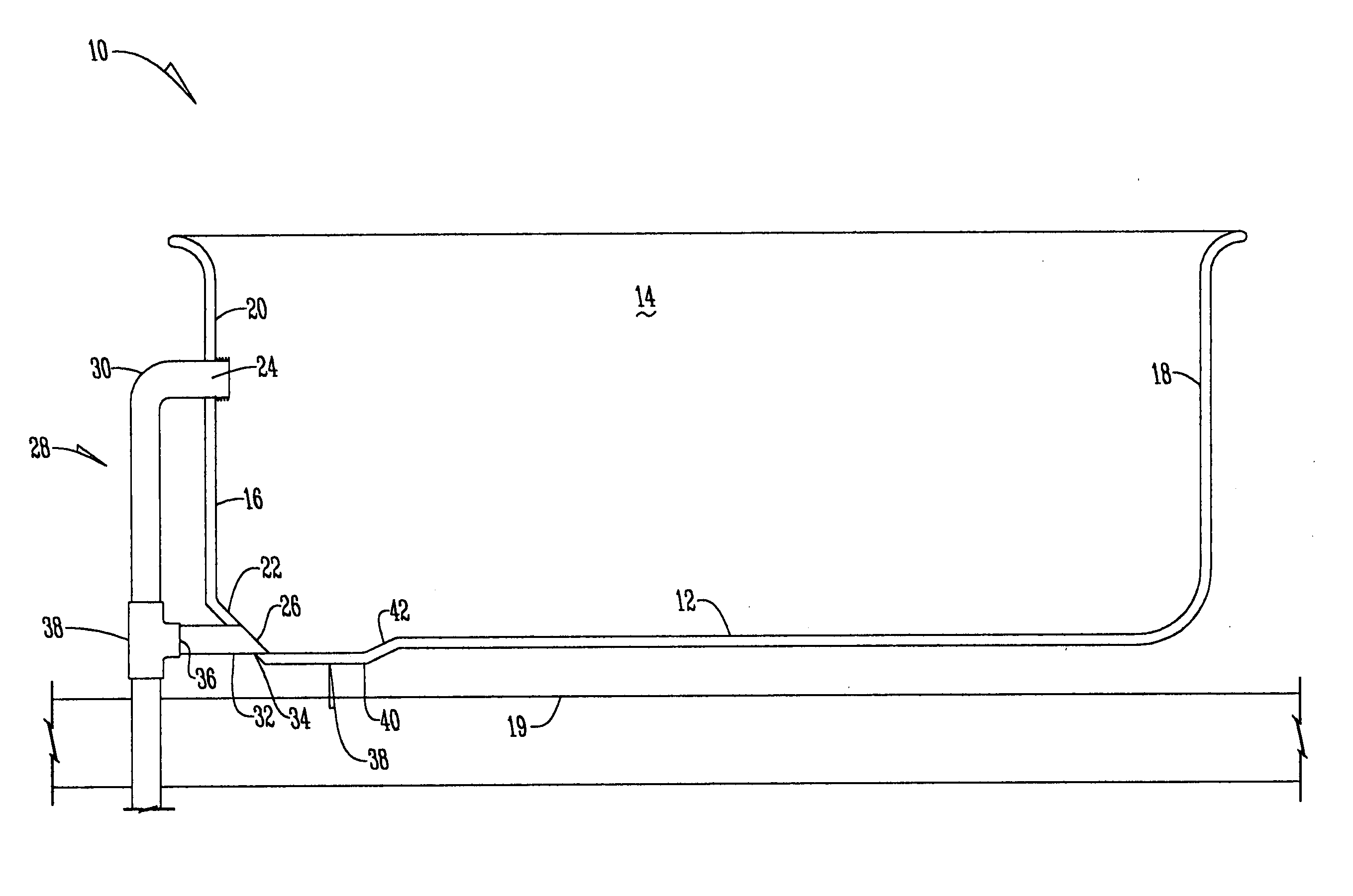
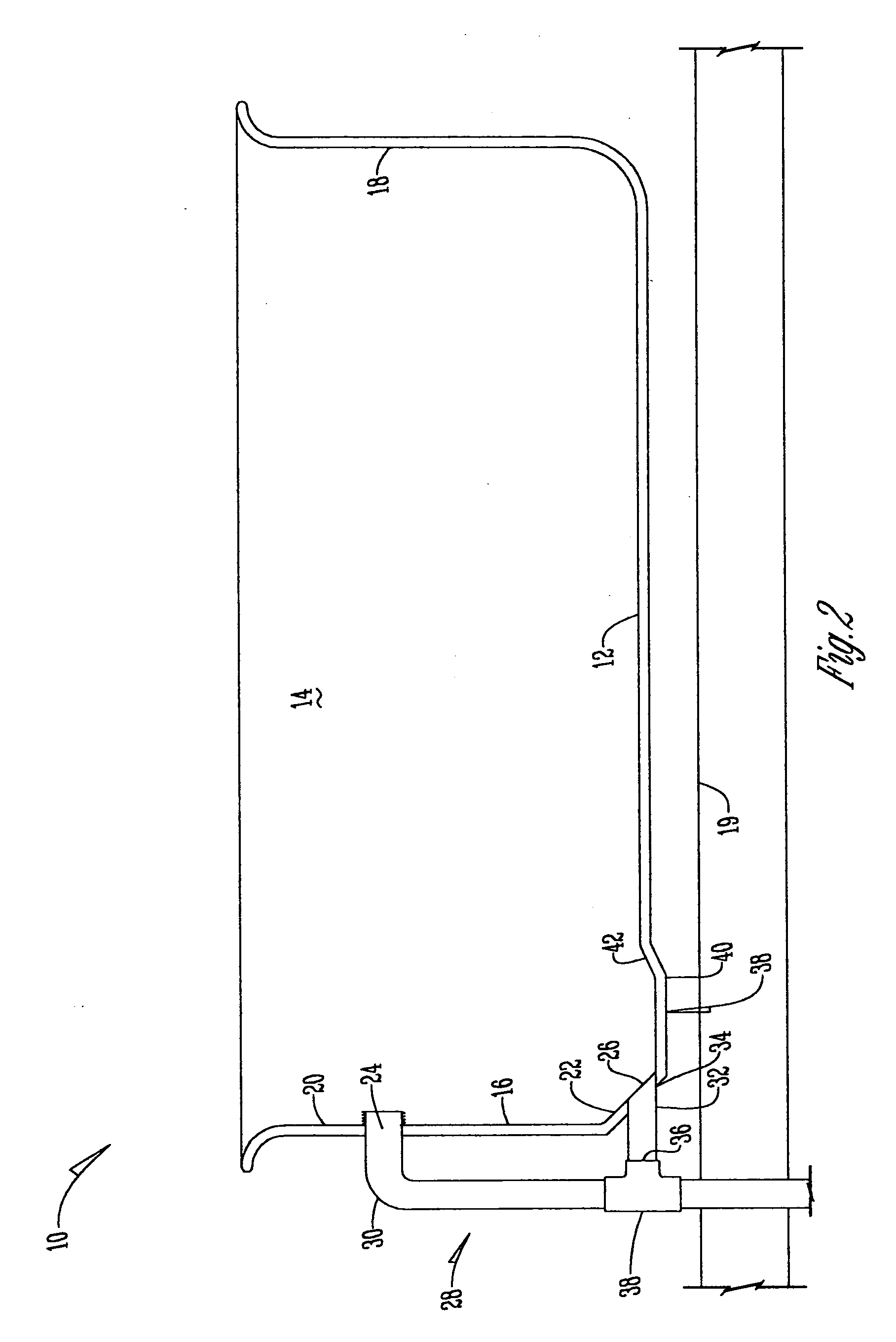
[0010] Referring to FIG. 2, the bathtub 10 of the present invention has a bottom 12, sidewalls 14, and end walls 16 and 18. The end wall 16 has a generally vertical portion 20 and a tapered or angled portion 22 that terminates in the bottom 12. Positioned within the vertical portion 20 is an overflow port 24 and positioned within the angled portion 22 of the end wall 16 is a drain port 26.

[0011] Connected to the bathtub 10 is a drain assembly 28 having an overflow pipe 30 that is connected to the overflow port 24 in any conventional manner. The drain assembly 28 also has a drain pipe 32 that is connected to the drain port 26 at a first end 34 and is connected to the overflow pipe at a second end 36. The drain pipe 32 is connected to the overflow pipe 30 in any conventional manner such as integrally formed or connected by a T-bar 38 as shown in FIG. 2. The first end 34 of the drain pipe 32 may be angled to fit the drain port 26 or a connector (not shown) is used to connect a convent...


PUM


Abstract

A low profile bathtub assembly having a bathtub with a bottom, side walls, and end walls wherein the first end wall has an overflow port and an angled portion having a drain port with both the drain port and overflow port fluidly connected to a drain assembly.

Description

BACKGROUND OF THE INVENTION [0001] The present invention is directed toward a low profile bathtub assembly and more specifically to a bathtub that eliminates the need to cut a groove in the floor during installation. [0002] Bathtubs are well known in the art and are used with drain assemblies generally having a drain pipe with a drain elbow that extends below the bottom of the tub and is connected to an overflow pipe as shown in FIG. 1. To install the drain assembly, traditionally, a plumber will cut a slot in the bathroom floor to accommodate the drain elbow and reduce the possibility of bumping or damaging the elbow when the tub is placed in its final location. This process not only is expensive, but also is time consuming. Accordingly, there is a need for a bathtub that allows faster and easier installation of the drain assembly. [0003] Therefore, a primary object of the present invention is to provide a bathtub that is easier and more economical to install. [0004] Yet another ob...

Claims


Application Information

Patent Timeline
IPC IPC(8): A47K3/02
CPCA47K3/02
Inventor BALL, WILLIAM T.
Owner WCM IND INC
Features
  • Generate Ideas
  • Intellectual Property
  • Life Sciences
  • Materials
  • Tech Scout
  • Unparalleled Data Quality
  • Higher Quality Content
  • 60% Fewer Hallucinations
Learn More