
Farm tractor lift arm lock

a technology for lifting arms and tractor, which is applied in the direction of agricultural tools and machines, adjusting devices, agricultural machines, etc., can solve the problems of inconvenient replacement, inconvenient control of the dragging of the tractor, and insufficient adjustment, so as to keep the angle between the arms constant

Inactive Publication Date: 2006-05-11
WARLICK HARLEY
View PDF27 Cites 6 Cited by
  • Summary
  • Abstract
  • Description
  • Claims
  • Application Information

AI Technical Summary

Benefits of technology

[0018] It is an aspect of the invention to provide improved elements and arrangements thereof for the purposes described which is inexpensive, dependable and fully effective in accomplishing its intended purposes.

Problems solved by technology

A problem with the three-point hitch is that the lift arms (sometimes referred to as “links”) sway back and forth, making it difficult to control the implement being dragged by the tractor.
The swaying of the links also puts an inordinate amount of stress on the pivot points, usually a floating ball, at each end of the links and wears out the floating balls so that they need to be frequently replaced.
The related art does not reveal a device that simply locks the links in place and does not allow them to move.
U.S. Pat. No. 2,727,756, issued Dec. 20, 1955 to Charley van Carlile, describes a tractor hitch adjuster that is designed to adjust and maintain the angularity of the towing arms, but is not designed to reduce sway.

Method used


Image

  • Farm tractor lift arm lock
  • Farm tractor lift arm lock
  • Farm tractor lift arm lock

Examples


Embodiment Construction

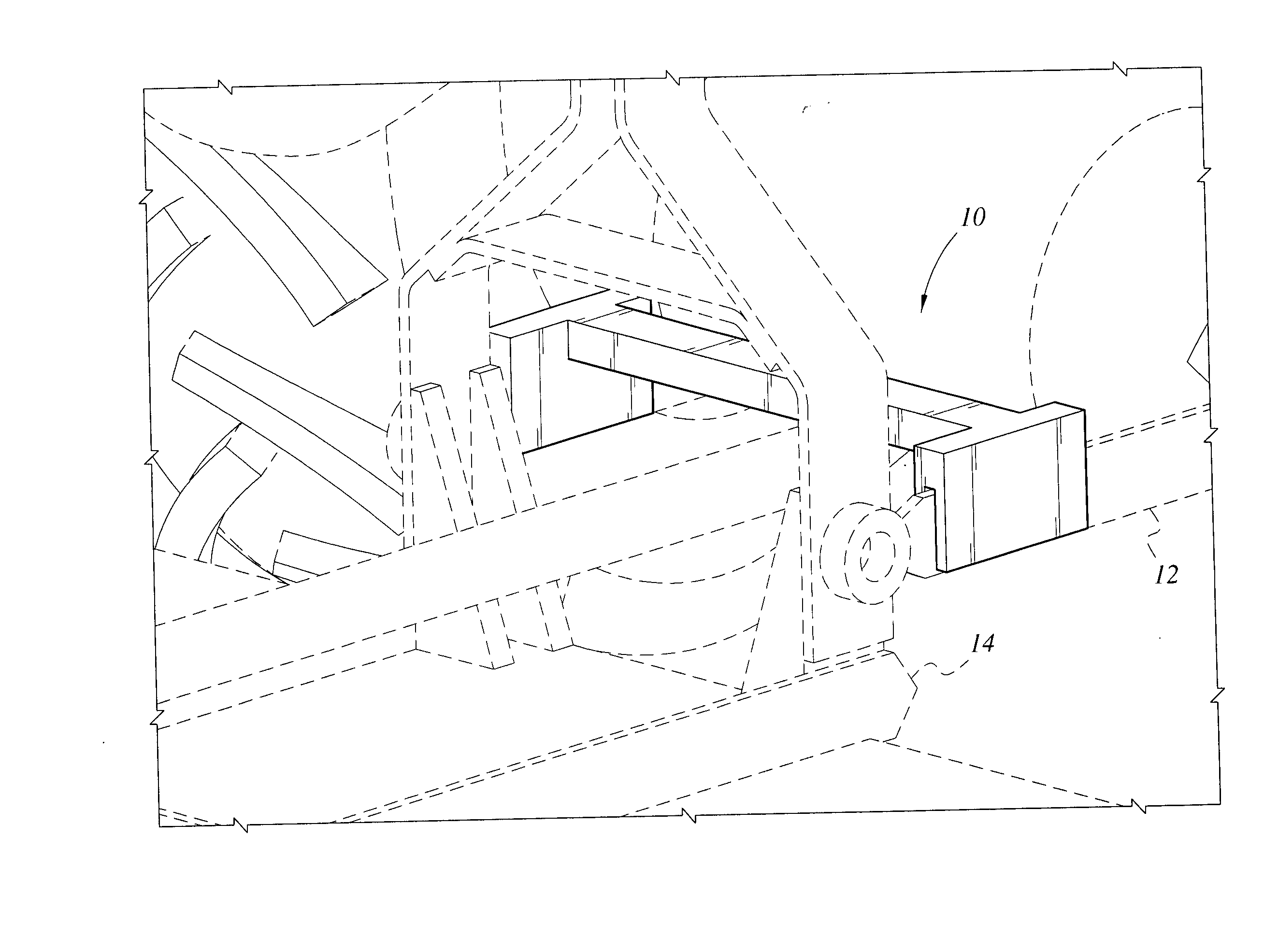
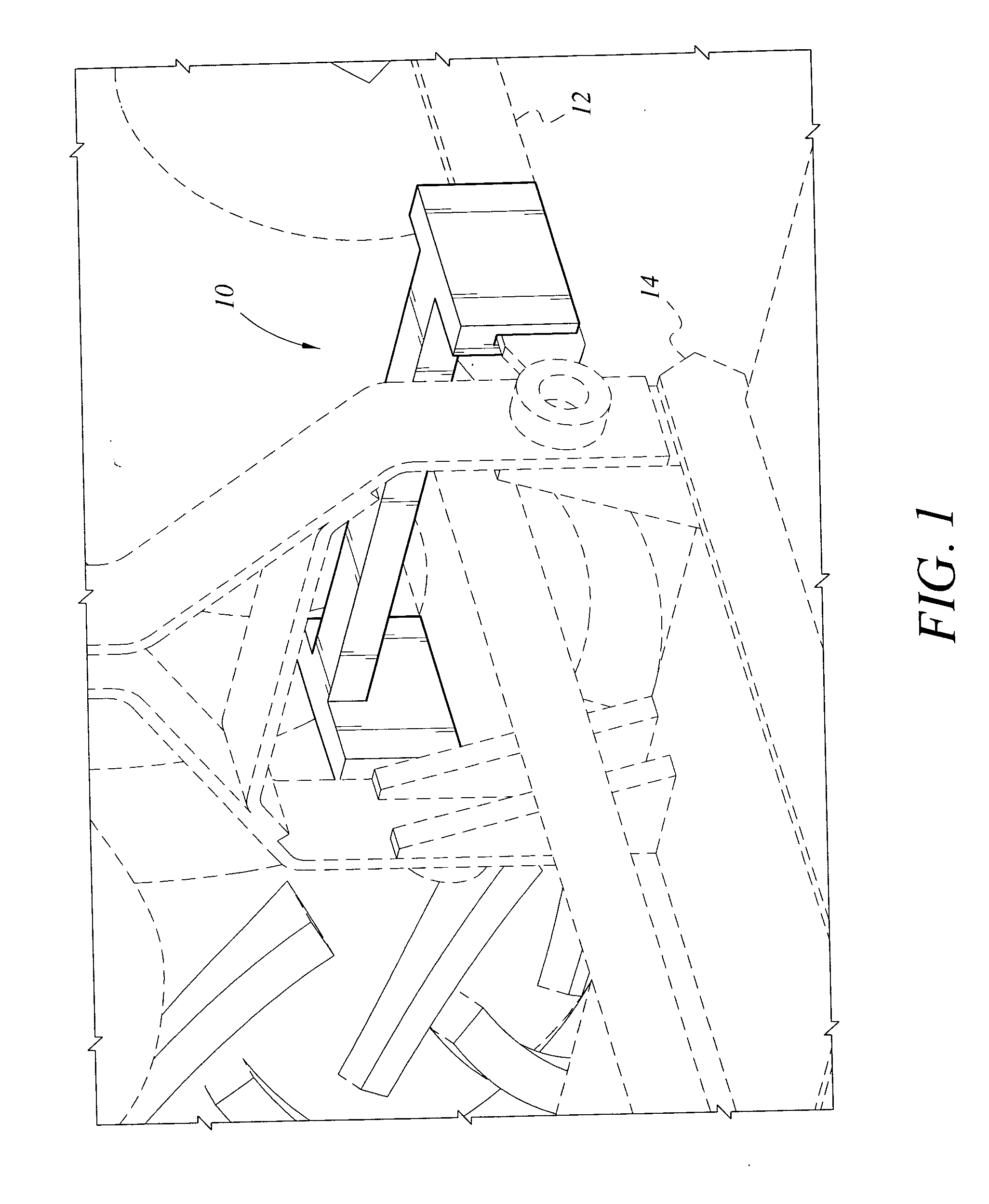
[0030] The present invention is a farm tractor lift arm lock, designated generally as 10 in the drawings. FIG. 1 shows the farm tractor lift arm lock 10 in place over the lift arms 12 of a tractor with a three-point hitch pulling a rock rake 14.

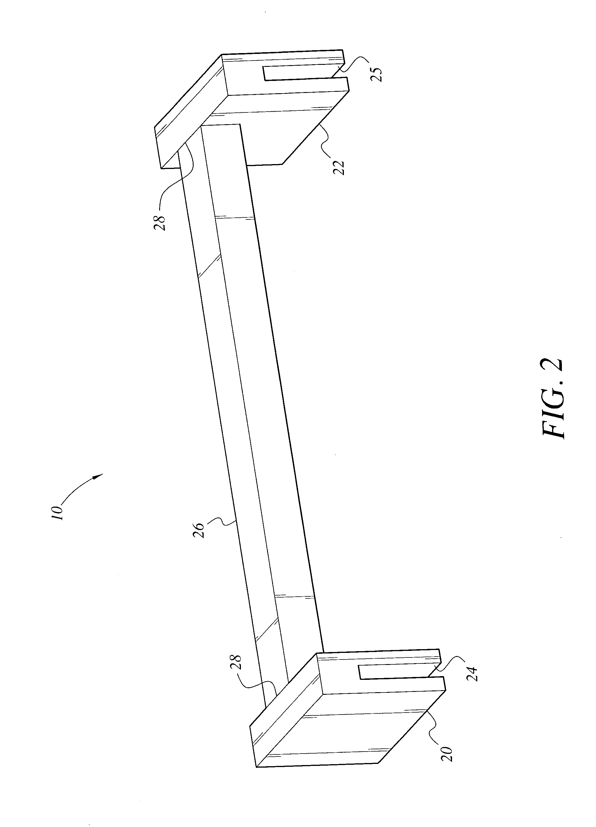
[0031]FIGS. 2-4 show the farm tractor lift arm lock 10 in its most simple form. Brackets 20 and 22 are attached at each end 28 of the anti-sway bar 26. Brackets 20 and 22 are have respective downward opening slots 24 and 25 defined in their respective bottom ends which enable the lift arm lock 10 to be placed over the lift arms of a three-point hitch and lock the arms 12 into place by a friction fit. By locking the arms in place, the load connected to the three-point hitch is prevented from swaying laterally and wear to the pivot points of the three-point hitch is greatly reduced. As shown, the anti-sway bar 26 is an elongate element of rigid metal bar stock, which may be solid or tubular. The anti-sway bar 26 may take the shape of pipe or a...


PUM


Abstract

The farm tractor lift arm lock is an anti-sway brace for a tractor that keeps the lift arms of a traditional three-point hitch from spreading excessively and keeps the angle between the arms constant. Two brackets attach to each of the lift arms and a rigid anti-sway bar extends laterally between the brackets, keeping the brackets, and thus the lift arms, from moving laterally relative each other. The farm tractor lift arm lock is made of metal and can either have the brackets welded to the ends of the anti-sway bar or can be of one-piece construction.

Description

CROSS-REFERENCE TO RELATED APPLICATION [0001] This application claims the benefit of U.S. Provisional Patent Application Ser. No. 60 / 558,997, filed Apr. 5, 2004.BACKGROUND OF THE INVENTION [0002] 1. Field of the Invention [0003] The present invention relates generally to mechanical mounting devices suitable for use with agricultural tractors, and more particularly to a lift arm lock for keeping the lift arms of a three-point hitch in a stable position, thereby reducing sway and reducing wear to the pivot points of the hitch. [0004] 2. Description of the Related Art [0005] A three-point hitch is used on many agricultural tractors in order to drag farm implements, such as plows, rippers, rock rakes, and hay rakes, behind the tractor. A problem with the three-point hitch is that the lift arms (sometimes referred to as “links”) sway back and forth, making it difficult to control the implement being dragged by the tractor. The swaying of the links also puts an inordinate amount of stress...

Claims


Application Information

Patent Timeline
Patent Type & Authority Applications(United States)
IPC IPC(8): A01B59/043
CPCA01B59/041
Inventor WARLICK, HARLEY
Owner WARLICK HARLEY
Learn More