Split type instrument ball valve with long service life

A split-type, long-life technology, applied in valve devices, cocks including cut-off devices, engine components, etc., can solve the problems affecting the transportation and use of media in the pipeline, control handle opening, bumping and other problems, and achieve the locking and unlocking process. Convenient and fast effects

Active Publication Date: 2018-12-18
JIANGSU HUATAI ELECTRIC POWER ELECTRONICS INSTR
View PDF5 Cites 0 Cited by
  • Summary
  • Abstract
  • Description
  • Claims
  • Application Information

AI Technical Summary

Problems solved by technology

[0008] Although this kind of instrument ball valve can ensure that the pressure in the valve body is always in a balanced state, and the installation is more convenient, the gas transmission is more stable and smooth, but because this kind of valve is often installed outdoors, after the control handle is closed, it is easy to be used by the outside world. The small animal bumped crookedly, or the control handle is opened due to misoperation by unrelated personnel, which affects the transportation and use of the medium in the pipeline

Method used


Image

  • Split type instrument ball valve with long service life
  • Split type instrument ball valve with long service life
  • Split type instrument ball valve with long service life

Examples


Embodiment 2

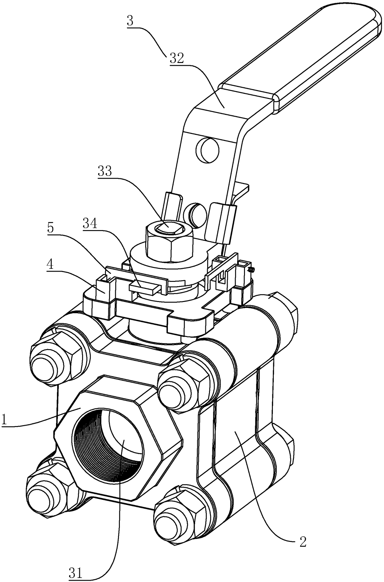
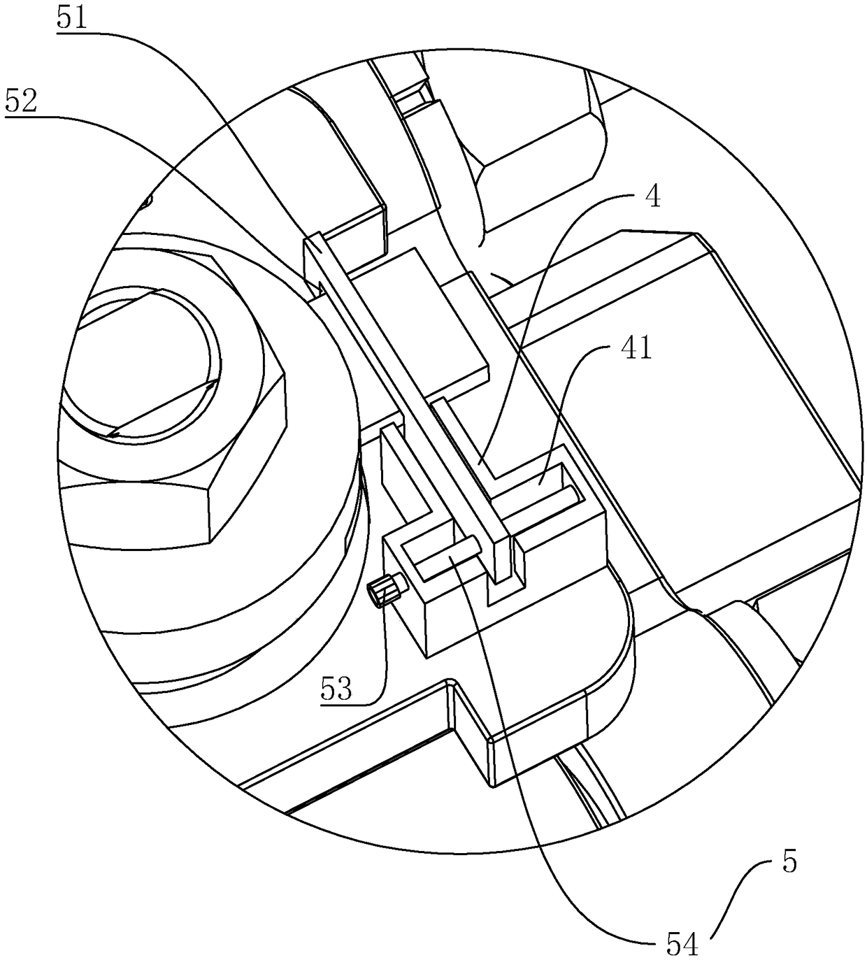
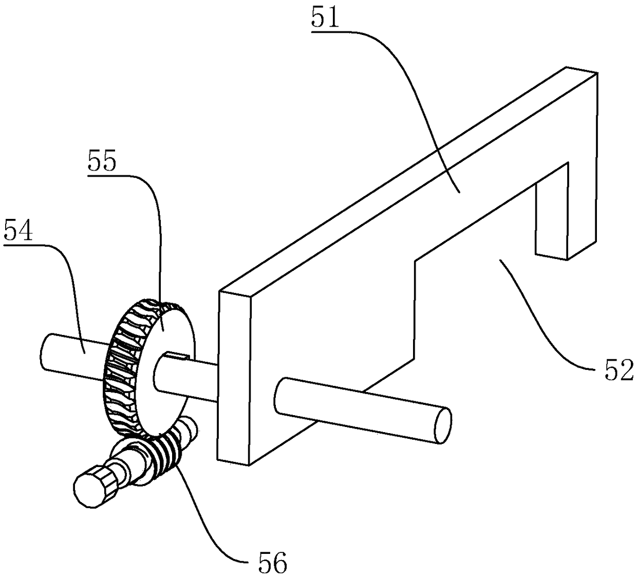
[0032] Embodiment 2, a high service life split type instrument ball valve, such as figure 1 and image 3 As shown, the difference from Embodiment 1 is that a locking worm gear 55 is fixed coaxially on the rotating shaft 54, and a locking worm 56 parallel to the rotating shaft 54 ​​is rotatably connected in the locking groove 41. The locking worm gears 55 are engaged with each other. The end of the locking worm 56 facing away from the locking rod 34 penetrates the locking block 4 and extends to the outside world, and the end located at the outside is fixed with a rotating knob 57 .

[0033] When the control handle 32 is rotated to the designated position, the operator can turn the rotary knob 57 to drive the locking worm 56 and the locking worm wheel 55 to rotate, thereby linking the rotation shaft 54 ​​and the locking rod 51 to rotate, to achieve the purpose of locking and fixing the control handle 32; The self-locking property of the worm gear can keep the rotating shaft 54...

Embodiment 3

[0034] Embodiment 3, a high service life split instrument ball valve, such as figure 1 and Figure 4 As shown, the difference from Embodiment 1 or 2 is that the locking member 5 includes an accommodating groove 42 opened in the middle of the locking block 4, and the accommodating groove 42 is slidably connected in the vertical direction with a locking plate 6, which locks the The ends of the plate 6 are correspondingly arranged in a hook shape, and the height of the locking plate 6 is greater than the height of the locking rod 34 .

[0035] like figure 1 and Figure 4 As shown, the locking member 5 includes a locking gear 62 rotatably connected to the accommodating groove 42 and a locking rack 61 fixed on the locking plate 6. The locking rack 61 and the locking gear 62 mesh with each other and are perpendicular to the Set on a horizontal plane, the locking gear 62 is rotatably connected in the accommodating groove 42 through the intermediate shaft 63 , and the rotating shaft ...


PUM


Abstract

The invention discloses a split type instrument ball valve with the long service life, and relates to the technical field of instrument valves. The split type instrument ball valve with the long service life comprises a valve body pipeline, a valve base and a control part, wherein the valve base and the control part are connected to the valve body pipeline. The control part comprises a control ball and a control handle. A control rod is connected to the valve base in a rotating mode, the control handle is integrally arranged on the control rod, and one end of the control handle penetrates through the control rod to form a locking rod. Two locking blocks which are used for limiting the rotation angle of the locking rod are arranged on the valve base, and a right angle is formed between thetwo locking blocks and the control rod. Locking parts which are used for clamping the locking rod are arranged on the portions, corresponding to the locking blocks, of the valve base, and the two locking parts are arranged in the mode of corresponding to the locking blocks and can lock the control handle. The phenomenon that due to the fact that small animals in the outside world impact on the valve, or the valve is subjected to misoperation of irrelevant personnel, the valve is opened and closed is avoided, the phenomenon that utilization of media in the pipeline is affected is avoided, and the locking and unlocking process is relatively convenient and fast.

Description

technical field [0001] The invention relates to the technical field of instrument valves, in particular to a high-service-life split-type instrument ball valve. Background technique [0002] An instrument valve is a pipeline accessory. It is a device used to change the passage section and the flow direction of the medium and control the flow of the conveying medium. The sealing performance of the instrument valve refers to the ability of each sealing part of the instrument valve to prevent the leakage of the medium, which is the most important technical performance index of the instrument valve. [0003] There are three sealing parts of the instrument valve: the contact between the opening and closing parts and the two sealing surfaces of the valve seat; the matching place between the packing and the valve stem and the stuffing box; the connection between the valve body and the bonnet. The leakage in the former part is called internal leakage, which is commonly referred to...

Claims


Application Information

Patent Timeline
Patent Type & Authority Applications(China)
IPC IPC(8): F16K5/06
CPCF16K5/0647
Inventor 陆超陈龙
Owner JIANGSU HUATAI ELECTRIC POWER ELECTRONICS INSTR
Why Eureka
Try Eureka