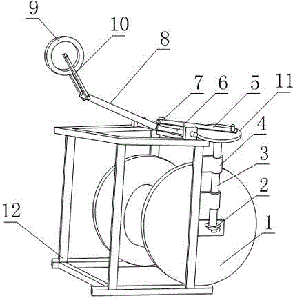
Take-up device enabling cable to be arranged uniformly
A winding device and uniform technology, applied in the directions of transportation and packaging, transportation of filamentous materials, thin material handling, etc., can solve the problems of unfavorable winding efficiency, winding quality and volume of winding rollers, etc. Wire quality, fast winding speed, light weight effect
- Summary
- Abstract
- Description
- Claims
- Application Information
AI Technical Summary
Problems solved by technology
Method used
Image
Examples
Embodiment 1
[0020] Such as figure 1 , a winding device for uniform wiring, comprising a frame 12 and a wire wheel 1 fixed on the frame 12, the wire wheel 1 is also connected with a driving motor for driving the wire wheel 1 to rotate around its axis, so The frame 12 is also provided with an adjusting device for realizing the uniform distribution of cables on the wire pulley 1;
[0021] The adjustment device includes a slide bar 6, a sliding sleeve 7 sleeved on the slide bar 6, a lead wheel frame 10, a lead wheel 9, a bolt seat 8, a reversing shaft 3, a bevel gear pair 2 and a drive rod 5. The axis of the slide bar 6 is parallel to the axis of the wire wheel 1, one end of the bolt seat 8 is fixedly connected with the sliding sleeve 7, the other end of the bolt seat 8 is bolted to the lead wheel frame 10, and the lead wheel frame 10 is opposite to the bolt seat 8 The included angle is adjustable, and the lead wheel 9 is fixed on the lead wheel frame 10;
[0022] The frame 12 is also provi...
Embodiment 2
[0025] The present embodiment is further limited on the basis of embodiment 1, as figure 1 , in order to make the reversing shaft 3 move through the compact brake sleeve 7 of the driving rod 5 during the rotation, the reversing shaft 3 is also fixed with a drive disc 11 perpendicular to the reversing shaft 3, the driving A column is fixed on the disk 11 and the sliding sleeve 7, and a bearing is arranged on the column, and the inner rings of the two bearings are respectively fixedly connected with the corresponding columns, and the two ends of the driving rod 5 are respectively connected with the outer rings of the two bearings. Fixedly connected, and the two columns are parallel to the reversing shaft 3. Using the drive plate 11 to realize the excessive connection between the reversing shaft 3 and the drive rod 5 facilitates the realization that the center of gravity of the reversing shaft 3 deviates less from the axis of the reversing shaft 3, which is beneficial to the stab...
Embodiment 3
[0027] The present embodiment is further limited on the basis of embodiment 1, as figure 1 , in order to reduce the compressive stress of the sliding sleeve 7 and the sliding rod 6 when the driving rod 5 drives the sliding sleeve 7 to move along the sliding rod 6, the driving rod 5 and the sliding rod 6 are located in the same plane.
PUM
 Abstract
Description
Claims
Application Information
 - R&D
- Intellectual Property
- Life Sciences
- Materials
- Tech Scout
- Unparalleled Data Quality
- Higher Quality Content
- 60% Fewer Hallucinations
Browse by: Latest US Patents, China's latest patents, Technical Efficacy Thesaurus, Application Domain, Technology Topic, Popular Technical Reports.
© 2025 PatSnap. All rights reserved.Legal|Privacy policy|Modern Slavery Act Transparency Statement|Sitemap|About US| Contact US: help@patsnap.com

