Disinfecting system for a toilet

a technology for disinfecting systems and toilets, applied in the field of toilet seats and toilet bowls, can solve the problem that the system does not prevent the use of the toilet, and achieve the effect of being easily seen

Inactive Publication Date: 2006-05-11
MASCO CORP
View PDF5 Cites 36 Cited by
  • Summary
  • Abstract
  • Description
  • Claims
  • Application Information

AI Technical Summary

Benefits of technology

[0007] Additionally, an indicator light can be mounted to an opposing side of the toilet seat. When the toilet seat is lowered, the indicator light can

Problems solved by technology

Thus, the system does not

Method used


Image

  • Disinfecting system for a toilet
  • Disinfecting system for a toilet

Examples


Embodiment Construction

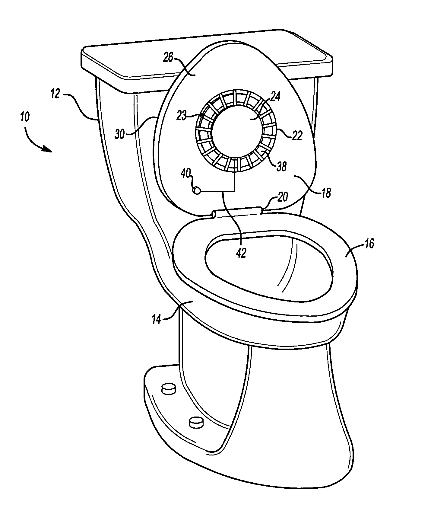
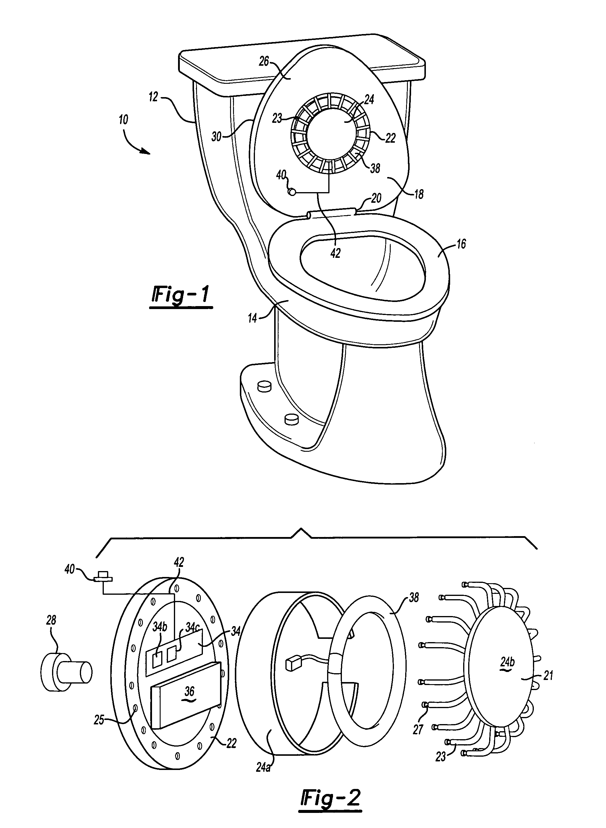
[0011]FIG. 1 illustrates a general view of an example disinfecting system 10 of the present invention. A toilet 12 has a toilet bowl 14. A toilet seat 16 and seat cover 18 are located on top of the toilet bowl 14. A hinge 20 allows the toilet seat 16 and seat cover 18 to be raised and lowered as needed.

[0012] The disinfecting system 10 includes a housing 22 and a housing cover 24. In one embodiment, the housing 22 is mounted on a first side of the seat cover 18. The housing 22 is mounted by known conventional means. For example, in one embodiment, an indicator 28 (Shown in FIG. 2) is mounted on an opposing side 30 of the seat cover 18. A through hole in the seat cover 18 allows wiring to connect the indicator 28 and the housing 22. The indicator 28 may also act as a fastener in retaining the housing 22 to the seat cover 18. The housing 22, and housing cover 24 may be made from stainless steel or other materials that are easily disinfected. The housing 22 may be mounted in other loc...


PUM


Abstract

The present invention provides a disinfecting system that uses ultraviolet light to disinfect a toilet seat and toilet bowl. The disinfecting system is mounted to a toilet seat cover. A control is used to activate the system when the toilet seat cover is lowered. An indicator light can be mounted to an opposing side of the toilet seat. The indicator light can be used to provide an indication that the system is currently operating or to indicate other status changes in the system.

Description

BACKGROUND OF THE INVENTION [0001] The present invention relates to an apparatus and method for disinfecting toilet seats and bowls. More particularly, the invention uses ultraviolet light to disinfect a toilet seat and bowl. [0002] Toilet seats and bowls require disinfecting to prevent the spread of infection and to maintain a clean bathroom environment. The most common method of sanitizing toilets is manually. However, frequent disinfecting is needed to maintain a sanitized toilet. Devices have been invented to reduce the frequency of required disinfecting and maintain a cleaner toilet. For example, paper coverings for the toilet seats are commonly used to provide a sanitized surface. However, this method is inconvenient for home use. [0003] Automated disinfecting systems have also been invented to reduce the efforts of the user. Known automated disinfecting systems require complicated mechanisms. These mechanisms are expensive to purchase and maintain. For example, a water or spr...

Claims


Application Information

Patent Timeline
IPC IPC(8): A61L2/10A47K13/30A61L2/24
CPCA47K13/302A61L2/10A61L2/24A47K13/30
Inventor LIM, SENG MING
Owner MASCO CORP
Why Eureka
Try Eureka