
State of charge indicator for battery

a technology of state of charge indicator and battery, which is applied in the direction of circuit monitoring/indication, transportation and packaging, and the arrangement of several simultaneous batteries, etc., can solve the problems of large errors as the battery ages, the state of charge change with time, and the use of cell or battery terminal voltage is not a practical means for measuring the state of charge of the battery

Inactive Publication Date: 2006-05-11
MATHEWS ASSOCS
View PDF16 Cites 612 Cited by
  • Summary
  • Abstract
  • Description
  • Claims
  • Application Information

AI Technical Summary

Benefits of technology

[0008] Therefore, it is an object of the present invention to provide a state of charge indicator for a battery that incorporates an automatic initialization or reset for different batteries and overcomes the disadvantages described above.

Problems solved by technology

In some cases, however, using the cell or battery terminal voltage is not a practical means for measuring the state of charge of the battery.
A problem develops, however, if the cell or battery configuration has a closed circuit voltage.
Further, the state of charge changes with time because of self-discharge within the battery cell.
Also, through numerous charge and discharge cycles in rechargeable batteries, any coulomb counter errors tend to be cumulative, resulting in large errors as the battery ages.
If the battery does not have a full charge and discharge cycle, however, large errors may result.
This is a complex calculation and is not always accurate.
In this type of configuration, it is difficult for the state of charge indicator to determine the state of charge of the battery.

Method used


Image

  • State of charge indicator for battery
  • State of charge indicator for battery
  • State of charge indicator for battery

Examples


Embodiment Construction

[0017] Different embodiments will now be described more fully hereinafter with reference to the accompanying drawings, in which preferred embodiments are shown. Many different forms can be set forth and described embodiments should not be construed as limited to the embodiments set forth herein. Rather, these embodiments are provided so that this disclosure will be thorough and complete, and will fully convey the scope to those skilled in the art. Like numbers refer to like elements throughout, and prime notation is used to indicate similar elements in alternative embodiments.

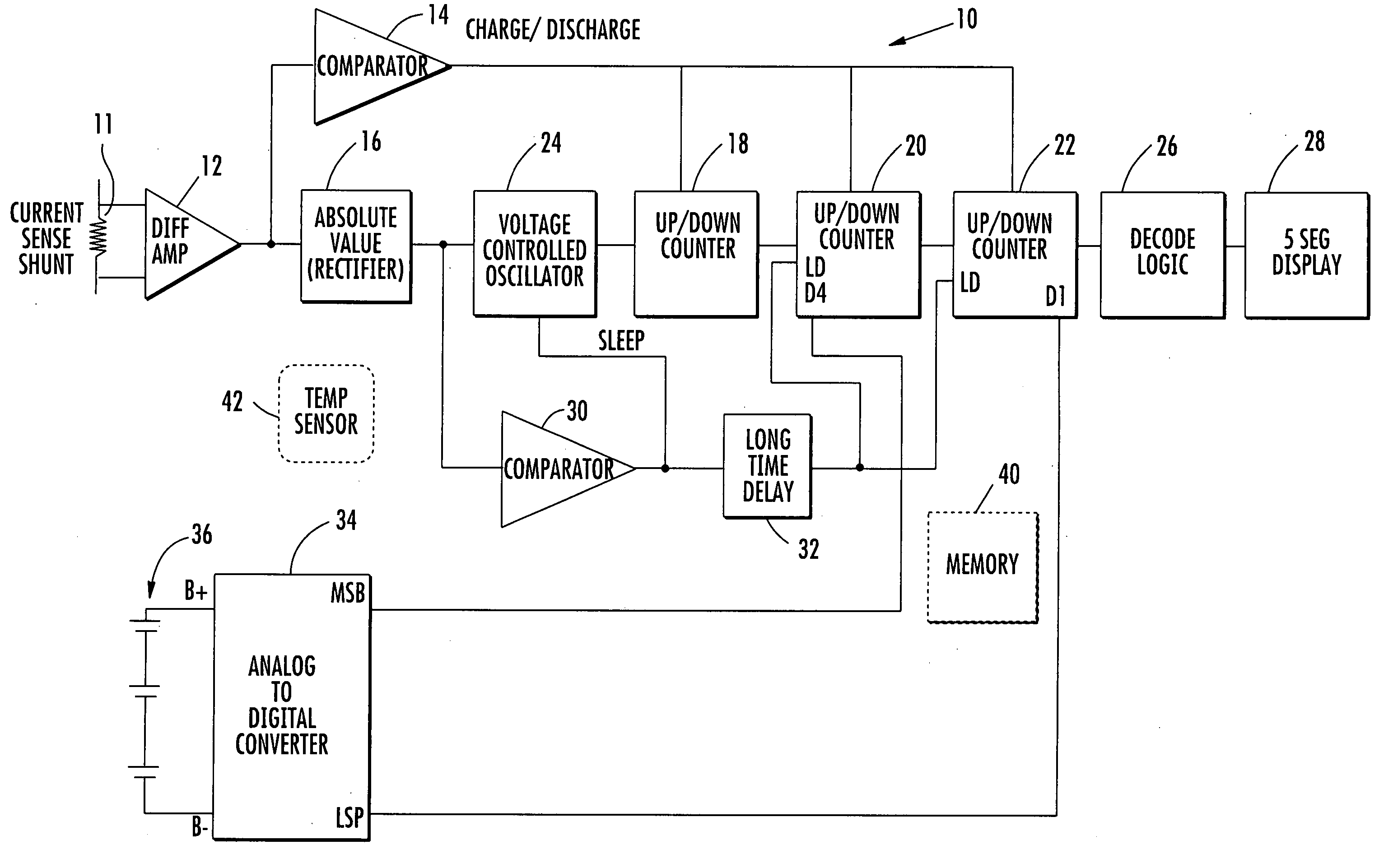
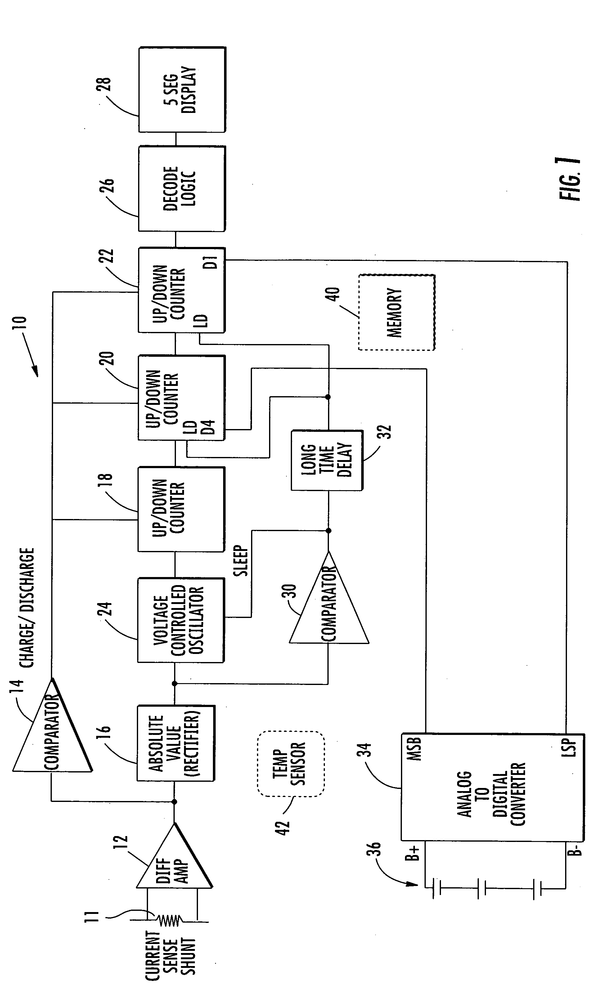
[0018] An exemplary battery state of charge indicator in accordance with one non-limiting example of the invention incorporates an automatic initialization or reset circuit. In one non-limiting example, a battery terminal voltage is continually measured. A current sensing circuit monitors the current, such as through a shunt resistor, and detects when the battery has been idle, i.e., neither charged nor discha...


PUM


Abstract

A state of charge indicator includes a current sensing circuit for sensing and converting charge or discharge current of a battery into a bipolar voltage. A counter circuit counts battery charge. A charge / discharge circuit is operatively connected to the current sensing and counter circuits and detects the voltage polarity from the current sensing circuit and sets the counter circuit to a count mode with an up or down count for a respective charge or discharge. A reset circuit is operative with the current sensing circuit, counter circuit and charge / discharge circuit for resetting the counter circuit to an actual state-of-charge of the battery after delay when the battery is idle representative of a battery open circuit voltage.

Description

RELATED APPLICATION [0001] This application is based upon prior filed copending provisional application Ser. No. 60 / 625,393 filed Nov. 5, 2004.FIELD OF THE INVENTION [0002] This invention relates to state of charge indicators for batteries. BACKGROUND OF THE INVENTION [0003] Many current battery systems require a state of charge indicator, sometimes referred to as a battery “gas gauge”, to indicate the state of charge, i.e., the available remaining energy left in the battery or in one or more battery cells forming the battery. One common system used for measuring the state of charge or remaining energy left in a battery is a coulomb counter. In typical circuit designs for these types of state of charge indicators using a coulomb counter, a current sensing circuit, such as a shunt resistor, senses the current from the battery. For example, the current can be measured into and out of a rechargeable battery, such as a lithium-ion battery as one non-limiting example. A monitoring circui...

Claims


Application Information

Patent Timeline
IPC IPC(8): H02J7/00
CPCH02J7/0016H02J7/0018H02J7/0047H02J7/0048
Inventor KAMENOFF, ROBERT
Owner MATHEWS ASSOCS
Learn More