Ink-jet recording device and ink supply unit suitable for it

a recording device and ink supply technology, applied in the direction of printing, transportation and packaging, thin material processing, etc., can solve the problems of affecting high-speed printing, reducing negative pressure, complicated wiring structure of each tube, etc., and achieves fine maintenance of negative pressure, high precision, and stable supply of ink to the recording head

a recording device and ink supply technology, applied in the direction of printing, transportation and packaging, thin material processing, etc., can solve the problems of affecting high-speed printing, reducing negative pressure, complicated wiring structure of each tube, etc., and achieves fine maintenance of negative pressure, high precision, and stable supply of ink to the recording head

US20060098062A1Inactive Publication Date: 2006-05-11SEIKO EPSON CORP

Image

  • Ink-jet recording device and ink supply unit suitable for it
  • Ink-jet recording device and ink supply unit suitable for it
  • Ink-jet recording device and ink supply unit suitable for it

Examples


Embodiment Construction

[0031] The present invention will be described in detail with reference to the illustrated embodiments.

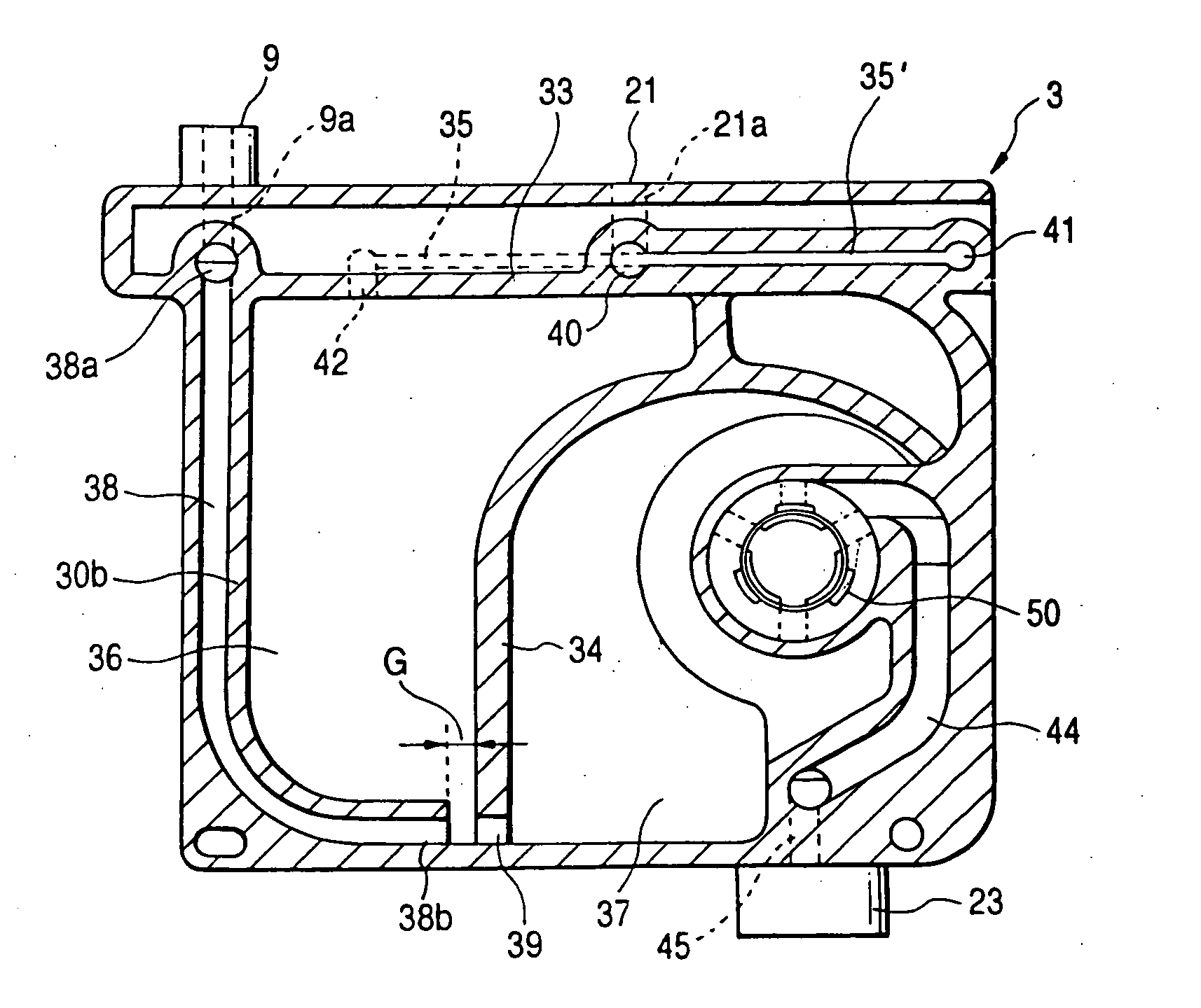
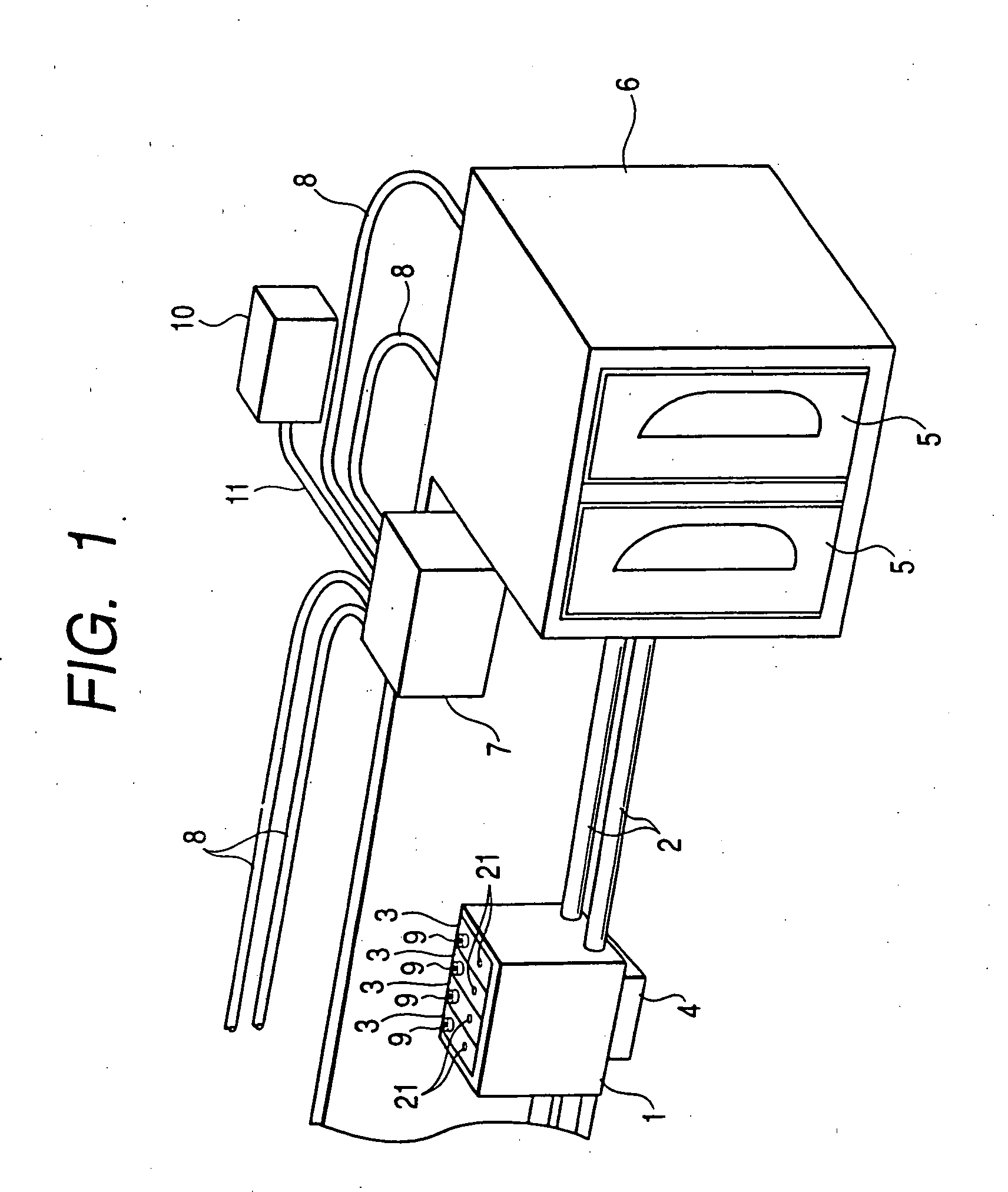
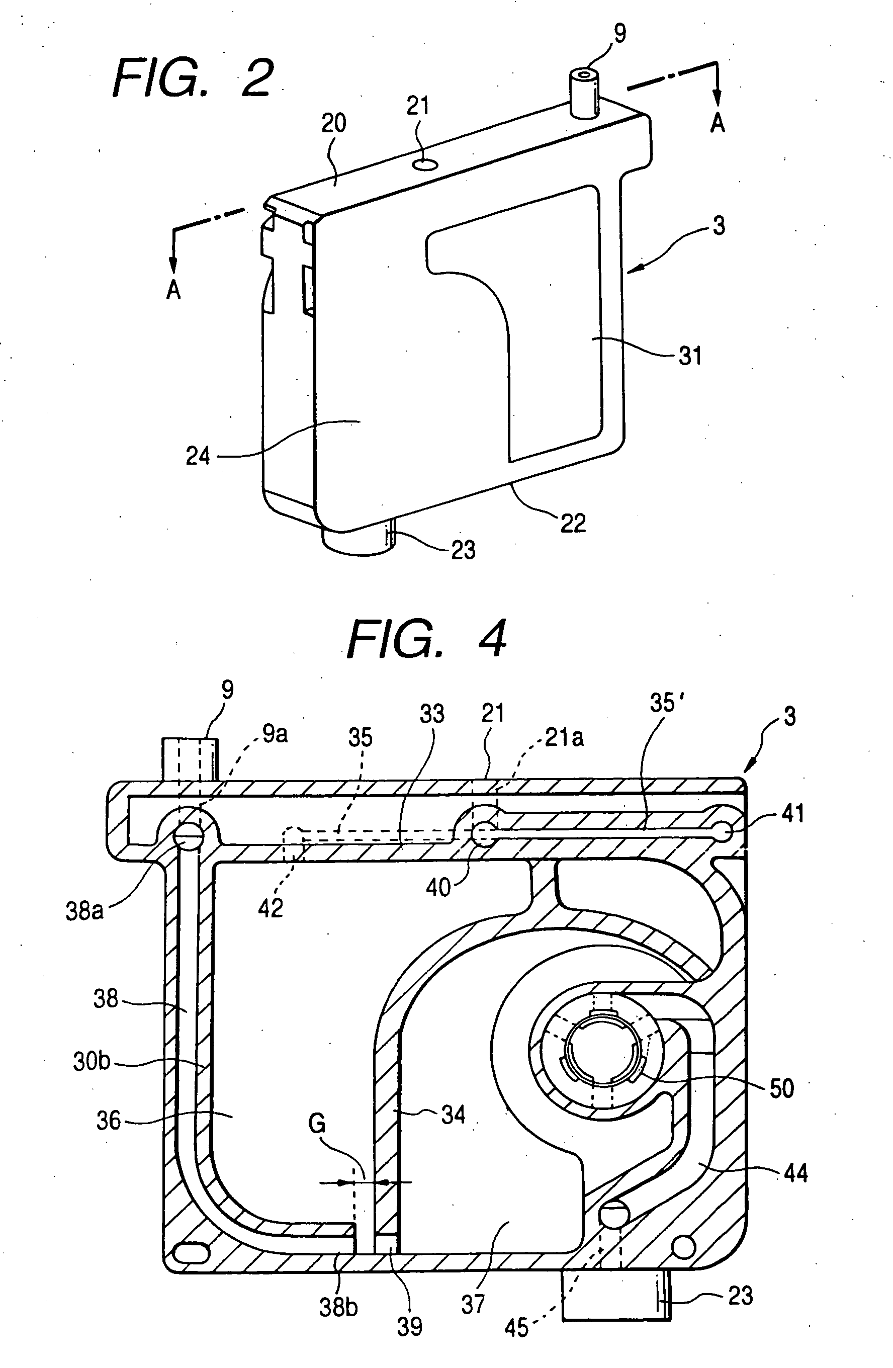
[0032]FIG. 1 shows an embodiment of the present invention. A carriage 1 is guided by a guide member 2, and can be reciprocated by driving means not shown. A plurality of ink supply units 3 (four ink supply units in this embodiment), each forming a feature of the present invention, are mounted on the upper part of the carriage 1, and a recording head 4 is provided on the lower surface of the carriage 1. A cartridge holder 6 for accommodating an ink cartridge 5 therein is disposed on each of the sides of an area where the carriage 1 is moved (only one side is shown in FIG. 1). An ink supplementing unit 7 is disposed above an non-printing area in the area where the carriage 1 is moved.

[0033] The ink supplementing unit 7 is connected to the ink cartridges 5 via tubes 8, and designed to connect to ink inlets 9 of the ink supply units 3 to inject ink up to a required level when the car...


PUM


Abstract

Ink maintained at a negative pressure state is supplied to an ink-jet recording head via an ink supply mechanism constructed as a differential pressure valve having a coil spring and a movable membrane normally contacted elastically with a valve seat by the coil spring.

Description

CROSS-REFERENCE TO RELATED APPLICATION [0001] This application is a continuation of copending application Ser. No. 10 / 819,756, filed Apr. 6, 2004, which is a division of copending application Ser. No. 09 / 525,477, filed Mar. 15, 2000.TECHNICAL FIELD [0002] The present invention relates to an ink-jet recording device composed of a carriage reciprocated in the direction of the width of a recording medium, an ink-jet recording head provided to the carriage and ink supply means mounted on the carriage for supplying ink to the recording head, more detailedly relates to technique for supplying ink while maintaining negative pressure applied to the recording head. BACKGROUND ART [0003] An ink-jet recording device used for printing a large number of pages is arranged, as disclosed in Japanese published examined patent application No. Hei4-43785 for example, such that an ink tank, e.g. a cassette, is installed in the body, and connected to an ink supply unit mounted on a carriage via an ink s...

Claims


Application Information

Patent Timeline
11 May 2006
Publication
US20060098062A1
IPC
B41J2/175; B41J2/18
CPC
B41J2/17503; B41J2/17509; B41J2/17513; B41J2/17523; B41J2/17556; B41J2/17566; B41J2/17596; B41J2/18
Inventors
MIYAZAWA, HISASHI