Ophthalmologic operation microscope

a technology of operation microscope and ophthalmology, which is applied in the field of ophthalmology, can solve the problems of deficiency of visual field of the operator and difficulty in observing the portions around the same, and achieve the effect of satisfying the visual field

Active Publication Date: 2006-05-11
KK TOPCON
View PDF8 Cites 8 Cited by
  • Summary
  • Abstract
  • Description
  • Claims
  • Application Information

AI Technical Summary

Benefits of technology

[0009] The present invention has been made in view of the above problem in the prior art. It is an object of the present invention to provide an ophthalmologic operation microscope that enables the operator to obtain a satisfactory visual field.

Problems solved by technology

Such reflection images lead to deficiency in visual field for the operator and constitute light spots in the observation image, making it rather difficult to observe the portions around the same.

Method used


Image

  • Ophthalmologic operation microscope
  • Ophthalmologic operation microscope
  • Ophthalmologic operation microscope

Examples


first embodiment

[0035] [General Construction of an Ophthalmologic Operation Microscope]

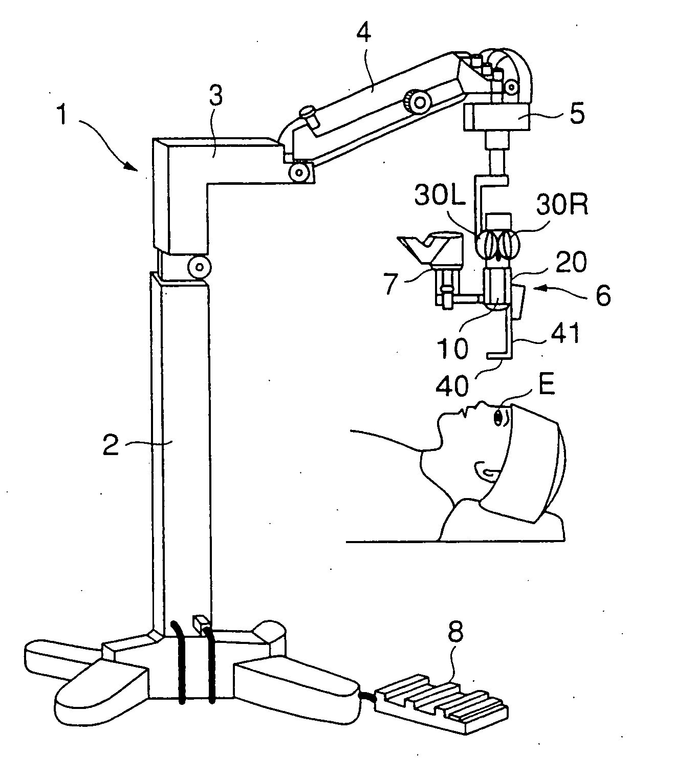
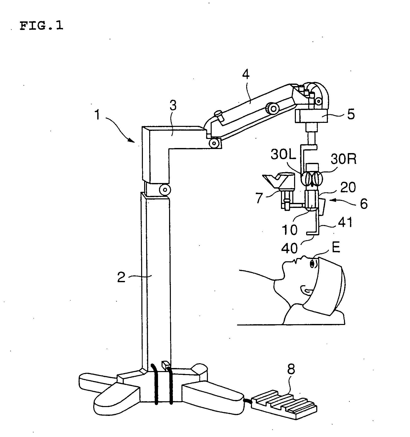
[0036]FIG. 1 shows the general construction of an ophthalmologic operation microscope 1 according to the first embodiment. This ophthalmologic operation microscope 1 is equipped with a column 2 for supporting the apparatus, a first arm 3 one end of which is connected to the upper end of the column 2, a second arm 4 one end of which is connected to the other end of the first arm 3, a drive device 5 connected to the other end of the second arm 4, an operator microscope 6 suspended from the drive device 5, an assistant microscope 7 disposed adjacent to the operator microscope 6, and a foot switch 8 for performing various operations with a foot. The operator microscope 6 and the assistant microscope 7 are driven three-dimensionally, i.e., vertically and horizontally, by the drive device S. Symbol E indicates an eye of the patient who is subjected to operation. Numeral 40 indicates a front lens disposed between the ob...

second embodiment

[0081] Next, another embodiment of the present invention will be described. This embodiment differs from the first embodiment in the construction for inclining the front lens. In the following description, the components that are the same as those of the first embodiment will be indicated by the same reference numerals. FIGS. 10A and 10B schematically show the construction of a part of the ophthalmologic operation microscope of this embodiment.

[0082]FIG. 10A shows the front lens 40 in the state of use. The ophthalmologic operation microscope of this embodiment is characterized by the construction of the accommodating portion 74 and the connection portion connected with the coil spring 54. The accommodating portion 74 and the coil spring 54 are rotatably connected by an axle 74a. By swinging the retaining arm 41, switching between use and non-use of the front lens 40 is effected. The portion where the accommodating portion 74 and the coil spring 54 are connected with each other is f...

third embodiment

[0084] While in the first and second embodiments described above the front lens 40, which is inclined, is arranged above the horizontal line, it is also possible to obtain the same effect as that of the first and second embodiments by inclining the front lens 40 so as to be situated below the horizontal line 1 as shown in FIG. 1A.

[0085] The third embodiment will be described in more detail. As indicated by the chain line in FIG. 11A, in the first and second embodiments, the front lens 40 is inclined so as to be situated above the horizontal line 1, which is at the level of the axle 41b (that is, such that the angle θ1 made by the retaining arm 41 (or observation axis) and the retaining plate 41a is an acute angle). In this embodiment, in contrast, the front lens 40′, indicated by the solid line, is rotated in the direction of the arrow Y so as to be situated below the horizontal line 1 (that is, such that the angle θ2 made by the retaining arm 41 (or observation axis) and the retai...


PUM


Abstract

Disclosed is an observation apparatus capable of eliminating in a suitable manner astigmatism and chromatic aberration generated in an observed image. The apex angle θ of a contact prism is input by operating an apex angle setting knob of a control panel, and the attachment angle thereof is input by operating an attachment angle setting knob. Based on the observation magnification recognized and the input apex angle θ, a control device determines the astigmatism correction amount for a left observation optical system and determines the astigmatism correction amount for the right observation optical system. Further, based on the input attachment angle, the axial angles of the astigmatisms of the left observation optical system and the right observation optical system are determined. Next, variable cross cylinder lens rotation drive devices are respectively controlled to rotate the respective cylinder lenses of the left and right observation optical systems to achieve the axial angle and correction amount as determined.

Description

RELATED APPLICATIONS [0001] This application is a divisional application of U.S. patent application Ser. No. 10 / 862,451, filed Jun. 8, 2004, which application claims priority under 35 U.S.C. § 119 of Japanese Application No. 2003-163931, filed Jun. 9, 2003, which are incorporated herein by reference.BACKGROUND OF THE INVENTION [0002] 1. Field of the Invention [0003] The present invention relates to an ophthalmologic operation microscope, and more particularly to an ophthalmologic operation microscope equipped with a front lens for observing the eyeground of the eye to be examined. [0004] 2. Description of the Related Art [0005] Usually, an ophthalmologic operation is conducted with microscopic observation. JP2002-350735A (paragraph [0016]-[0018], FIG. 6, FIG. 7, and FIG. 9) discloses an example of a microscope for such ophthalmologic operation. In the ophthalmologic operation microscope as disclosed in the above publication, a front lens is arranged between the objective lens and th...

Claims


Application Information

Patent Timeline
Patent Type & Authority Applications(United States)
IPC IPC(8): G02B21/06A61B3/13A61B3/15A61B19/00A61F9/007G02B21/00G02B21/18G02B21/22
CPCA61B3/132A61B3/156G02B21/0012G02B21/0032G02B21/22
Inventor KITAJIMA, NOBUAKI
Owner KK TOPCON
Why Eureka
Try Eureka