Method and apparatus to provide temporary peak power from a switching regulator

a switching regulator and temporary technology, applied in the field of electrical circuits, can solve the problems of large design volume, high cost, and infrequent use, and achieve the effect of reducing the number of devices, and increasing the cost of equipmen

Active Publication Date: 2006-05-11
POWER INTEGRATIONS INC
View PDF3 Cites 51 Cited by
  • Summary
  • Abstract
  • Description
  • Claims
  • Application Information

AI Technical Summary

Problems solved by technology

However, a maximum or peak output power is usually required for a relatively short duration and infrequently, for example to reverse the direction of a moving printer head or to spin a disk from startup to its rated speed.
Designers of power supplies for these applications are challenged to provide a wide range of power while conforming to conflicting requirements of efficiency, size, and cost.
Efforts to meet the requirements for continuous moderate power and short duration peak power from the same power supply usually lead to designs that are larger, heavier, and more costly than necessary if the load range were limited.

Method used


Image

  • Method and apparatus to provide temporary peak power from a switching regulator
  • Method and apparatus to provide temporary peak power from a switching regulator
  • Method and apparatus to provide temporary peak power from a switching regulator

Examples


Embodiment Construction

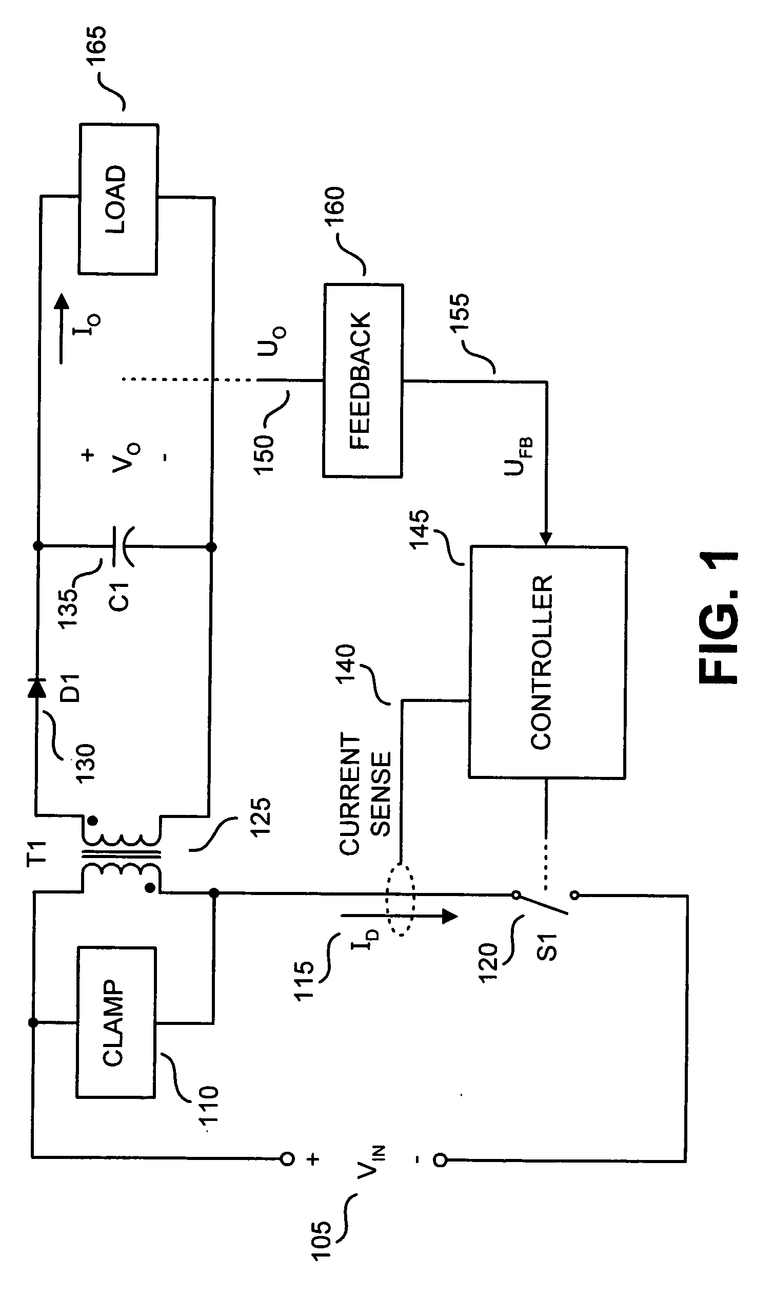
[0015] Embodiments of a power supply regulator that may be utilized in a power supply are disclosed. In the following description, numerous specific details are set forth in order to provide a thorough understanding of the present invention. It will be apparent, however, to one having ordinary skill in the art that the specific detail need not be employed to practice the present invention. Well-known methods related to the implementation have not been described in detail in order to avoid obscuring the present invention.

[0016] Reference throughout this specification to “one embodiment” or “an embodiment” means that a particular feature, structure, or characteristic described in connection with the embodiment is included in at least one embodiment of the present invention. Thus, the appearances of the phrases “in one embodiment” or “in an embodiment” in various places throughout this specification are not necessarily all referring to the same embodiment. Furthermore, the particular ...


PUM


Abstract

Various techniques directed to providing temporary peak power from a switching regulator are disclosed. In one aspect, a switching regulator includes a switch that is to be coupled between a power supply input and an energy transfer element of the power supply. A controller is coupled to be responsive to a feedback signal to be received from an output of the power supply. The controller is coupled to switch the switch in response to the feedback signal to regulate the output of the power supply. An oscillator is coupled to provide an oscillating signal to the controller to determine a maximum switching frequency of the switch. The oscillating signal is coupled to oscillate at a first frequency under a first moderate load condition at the power supply output. The oscillating signal is coupled to oscillate at a second frequency under a second peak load condition at the power supply output.

Description

BACKGROUND [0001] 1. Technical Field [0002] The present invention relates generally to electronic circuits, and more specifically, the invention relates to switched mode power supplies. [0003] 2. Background Information [0004] Many types of electronic equipment use varying amounts of power in normal operation. The range of power demanded from a power supply can be extreme, extending for example from a few milliwatts to nearly 100 watts. Large ranges of loading are common in equipment such as printers, digital video disc (DVD) recorders, and other products that require rapid activation of mechanical motion. Typically, a moderate continuous output power is required for a long duration, for example when a DVD disk is spinning continuously or the print head in a printer is moving across a page. However, a maximum or peak output power is usually required for a relatively short duration and infrequently, for example to reverse the direction of a moving printer head or to spin a disk from s...

Claims


Application Information

Patent Timeline
Patent Type & Authority Applications(United States)
IPC IPC(8): H02M3/335
CPCH02M3/33507
Inventor BAURLE, STEFANPOLIVKA, WILLIAM M.MATTHEWS, DAVID MICHAEL HUGH
Owner POWER INTEGRATIONS INC
Why Eureka
Try Eureka