
Pattern recognition apparatus and pattern recognition method

a pattern recognition and pattern recognition technology, applied in speech recognition, speech analysis, instruments, etc., can solve the problems of difficulty in matching feature points, difficulty in positioning, and difficulty in clear definition of feature points

Inactive Publication Date: 2006-05-11
KK TOSHIBA
View PDF0 Cites 26 Cited by
  • Summary
  • Abstract
  • Description
  • Claims
  • Application Information

AI Technical Summary

Benefits of technology

The invention provides a pattern recognition method that is nonparametric and has minimal positional deviation. The method includes inputting images of a learning object and a recognition object, calculating feature amount vectors of the images, setting a calculation range for calculating a probability distribution of the feature amount vectors, calculating the probability distribution of the feature amount vectors for the learning object, storing the probability distribution in association with the learning object, calculating a posterior probability that the recognition object is the learning object, and recognizing the recognition object based on the posterior probability. The invention also provides an apparatus for generating a pattern recognition dictionary. The technical effects of the invention include improved accuracy and efficiency in pattern recognition and reduced positional bias.

Problems solved by technology

However, the positioning may be difficult.
For example, clear definition of the feature points may be difficult or matching of the feature points may be difficult.
When positional deviation itself is a feature amount, feature information is lost because of the positioning.
Conversely, when the positioning is not performed, since a distribution of the pattern does not always match a model, recognition performance decreases.
Therefore, it is difficult to cope with a case in which there is positional deviation.
Since the determination is made based only on extremely local information of the pixel, recognition of a pattern may be unreliable.

Method used


Image

  • Pattern recognition apparatus and pattern recognition method
  • Pattern recognition apparatus and pattern recognition method
  • Pattern recognition apparatus and pattern recognition method

Examples


first embodiment

[0029] A first embodiment of the invention will be hereinafter explained with reference to the accompanying drawings.

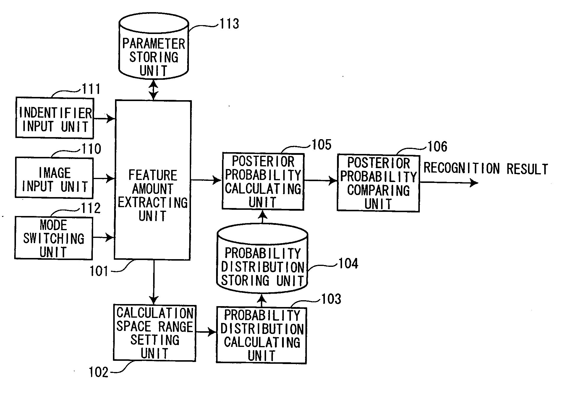
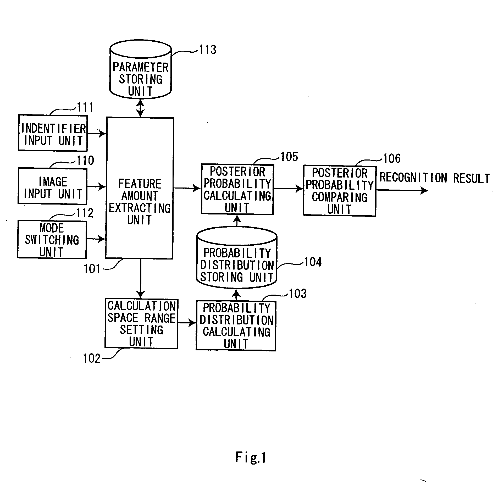
[0030]FIG. 1 is a block diagram of a pattern recognition apparatus in the first embodiment. The pattern recognition apparatus includes an image input unit 110 that inputs an image, an identifier input unit 111 that inputs identifiers of learning objects, a feature amount extracting unit 101 that extracts feature amount vectors of the image inputted and feature values the feature amount vectors, and a parameter storing unit 113 that stores data (information on the inputted image) used by the feature amount extracting unit 101 and data (parameters defining a feature amount vector space) generated by the feature amount extracting unit 101.

[0031] The pattern recognition apparatus also includes a calculation space range setting unit 102 that sets a range (a calculation space range), in which a probability distribution of the feature amount vectors is calculated in the fe...

second embodiment

[0081] A second embodiment of the invention will be hereinafter explained with reference to the accompanying drawings.

[0082] The pattern recognition apparatus in the first embodiment performs recognition by comparing a posterior probability of the class cj and posterior probabilities of other classes cg. However, it is not always possible to calculate feature amount vectors of all classes.

[0083] In the case of a monitoring system that recognizes and distinguishes a normal state and an abnormal state, it is easy to obtain a feature amount vector of a normal state class c0 corresponding to the normal state. However, it is not rare that it is difficult to obtain a feature amount vector of an abnormal state class cI corresponding to the abnormal state. For example, it is not realistic to set fire to a building being monitored in order to cause a system for monitoring a building to learn a fire state.

[0084] In the case of such a system, processing for judging that a state is abnormal ...

third embodiment

[0094] A third embodiment of the invention will be hereinafter explained with reference to the accompanying drawings.

[0095] The recognition methods based on a posterior probability explained in the first and the second embodiments is the nonparametric method of not assuming a distribution model of a pattern. In these methods, as the amount of learning data increases, the performance increases and generally the method requires a relatively large number of learning data in order to obtain high performance.

[0096] On the other hand, in the parametric method represented by the subspace method, rather high performance is often obtained even if an amount of learning data is relatively small.

[0097] Thus, in the pattern recognition apparatus in this embodiment, improvement and stabilization of recognition performance are realized by combining other methods (e.g., the parametric method) with the pattern recognition apparatuses in the first and the second embodiments.

[0098]FIG. 11 is a blo...


PUM


Abstract

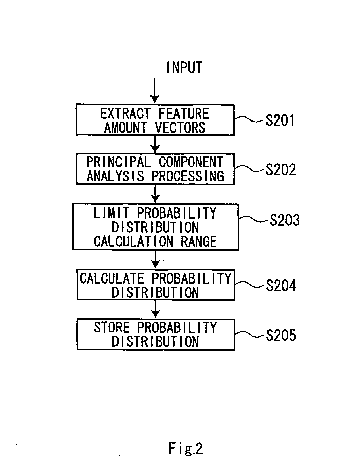
A feature amount extracting unit extracts feature amount vectors of an inputted image. A probability distribution calculator calculates a probability distribution of feature amount vectors in a calculation space range which is set by a calculation space range setting unit. A probability distribution storage stores the probability distribution in association with identifiers of learning objects. A posterior probability calculator calculates a posterior probability, which is a probability that a recognition object corresponds to each of the learning objects, using feature amount vectors calculated from an image of the recognition object and the probability distribution of the learning objects stored in the probability distribution storage. A posterior probability comparing unit compares posterior probabilities calculated and outputs a result of recognition of the recognition object.

Description

CROSS REFERENCES TO RELATED APPLICATIONS [0001] This application is based upon and claims the benefit of the prior Japanese Patent Applications: [0002] No.P2004-323115 filed on Nov. 8, 2004; and [0003] No.P2005-308933 filed on Oct. 24, 2005; the entire contents of which are incorporated herein by reference. TECHNICAL FIELD [0004] The present invention relates to a pattern recognition technique for detecting abnormality and detecting and identifying an object on the basis of pattern information such as an image. DESCRIPTION OF RELATED ART [0005] Conventionally, there has been proposed a method of recognizing and identifying an object according to a parametric method (e.g., M. Seki, et al., “A robust background subtraction method for changing background”, MIRU-2000, Vol. 2, pp. 403-408, July 2000). In the method, it is assumed that a distribution of a pattern follows a known model such as the Gaussian distribution. The subspace method is an example of this method. [0006] There has als...

Claims


Application Information

Patent Timeline
Patent Type & Authority Applications(United States)
IPC IPC(8): G10L15/14
CPCG06K9/6217G06F18/21
Inventor YOKOI, KENTARO
Owner KK TOSHIBA
Learn More