
Buckling-restrained diagonal brace using lapping and improved plugging connection

Inactive Publication Date: 2006-05-18
JEN CHIAO YU +1
View PDF4 Cites 60 Cited by
  • Summary
  • Abstract
  • Description
  • Claims
  • Application Information

AI Technical Summary

Benefits of technology

[0010] Accordingly, to overcome the foregoing disadvantages and limitations of conventional buckling-restrained diagonal braces, the present invention provides more efficient, economical, and convenient in installation seismic-proof, energy-dissipating diagonal braces.

Problems solved by technology

In addition, before their energy dissipation capacity is fully utilized, conventional diagonal bracing members would be broken due to excessively focused stress and strain.
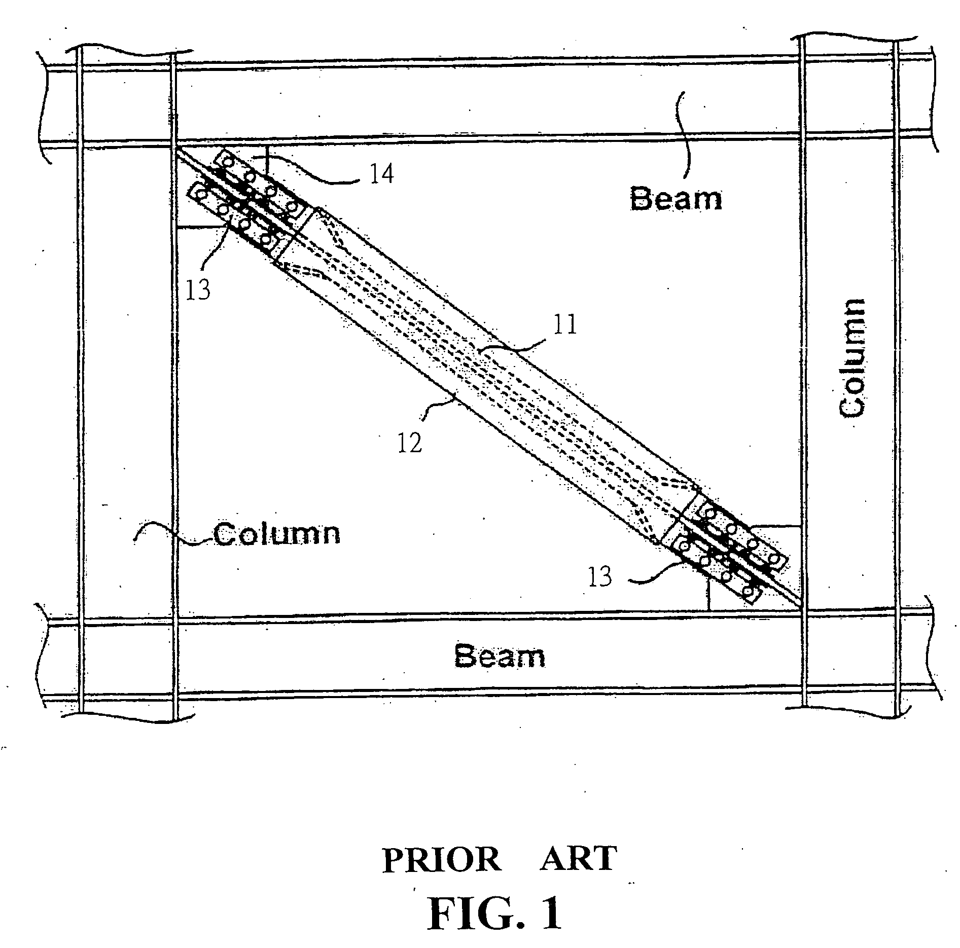
However, this kind of connection not only imposes a heavy welding workload, but also complicates and jams the connecting parts of the buckling-restrained diagonal braces.
Therefore, the installation of conventional buckling-restrained diagonal braces is very labor-intensive, time-consuming, operationally inefficient, and is more difficult to control the quality.
If the two band-like steel plates are not well spaced, and the length of the diagonal brace is often greater than the beam width or column height in a single slant direction, the installation efficiency is inevitably decreased and sometimes the installation is impossible.

Method used


Image

  • Buckling-restrained diagonal brace using lapping and improved plugging connection
  • Buckling-restrained diagonal brace using lapping and improved plugging connection
  • Buckling-restrained diagonal brace using lapping and improved plugging connection

Examples


Embodiment Construction

[0050] The following descriptions are of exemplary embodiments only, and are not intended to limit the scope, applicability or configuration of the invention in any way. Rather, the following description provides a convenient illustration for implementing exemplary embodiments of the invention. Various changes to the described embodiments may be made in the function and arrangement of the elements described without departing from the scope of the invention as set forth in the appended claims.

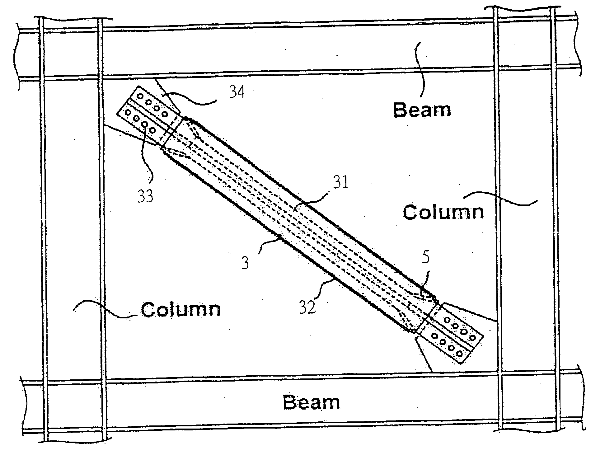
[0051] Besides improving the shortcomings of the conventional buckling-restrained diagonal braces, the present invention further provides various enhanced and innovative installations, which conform more closely to the requirements of seismic engineering and practical application. Please refer to FIGS. 4 to 13. The major features of the present invention are described as follows.

[0052] An embodiment of the present invention is a buckling-restrained diagonal brace using lapping connection. The ...


PUM


Abstract

A buckling-restrained diagonal brace is provided. The buckling-restrained diagonal brace mainly contains a core element and a restraining element. The core element is an assembly of a specific number of steel members having a specific shape whose cross-sectional dimension is determined based on the load requirement. The core element has a larger cross-section at the ends than at its medial section. The core element is encased in the restraining element. The restraining element manly contains a single or multiple steel tubes filled with concrete, mortar, or reinforcing members. The restraining element is to protect the core element so that it wouldn't be buckled and destructed under load. By using a lapping or an improved plugging type of connection to a structure frame, the buckling-restrained diagonal brace is able to yield steadily when loaded in both tension and compression and the buckling-restrained diagonal brace would have a full hysteretic curve. The buckling-restrained diagonal brace has a significantly enhanced ductility and energy dissipation capability, and is able to reduce vibration and to lower seismic impact.

Description

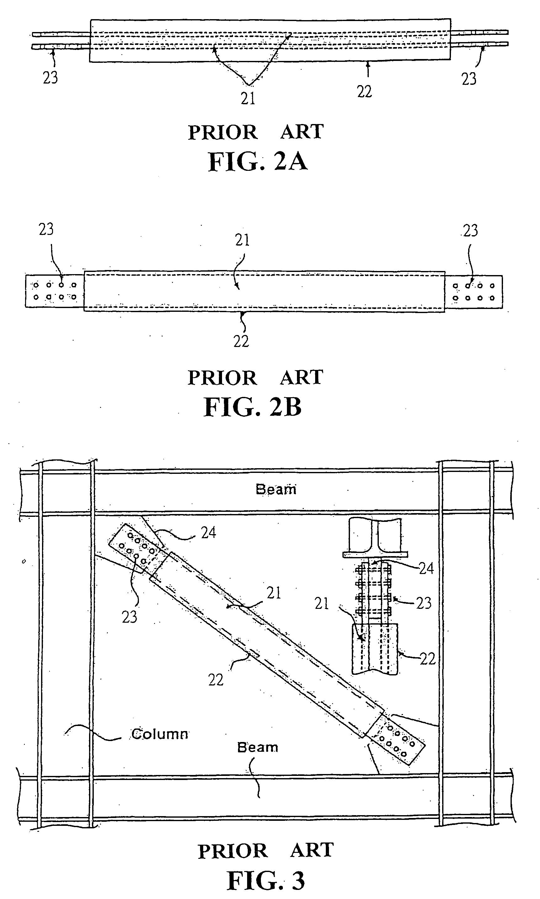
BACKGROUND OF THE INVENTION [0001] (a) Technical Field of the Invention [0002] The present invention generally relates to buckling-restrained diagonal braces and, more particularly, to buckling-restrained diagonal braces using lapping and improved plugging types of connection. [0003] (b) Description of the Prior Art [0004] Conventional diagonal bracing members would suffer global and local buckling when subjected to an axial force. The hysteretic curves of these conventional diagonal bracing members exhibit decreasing strength and contracting behaviors. In addition, before their energy dissipation capacity is fully utilized, conventional diagonal bracing members would be broken due to excessively focused stress and strain. As such, for many years, seismic engineering researchers have been investigating improvements to the performance of diagonal braces, and various buckling-restrained diagonal braces are proposed to replace and enhance conventional diagonal braces. [0005] As shown i...

Claims


Application Information

Patent Timeline
IPC IPC(8): E04H9/02
CPCE04H9/02E04H9/028E04H9/0237
Inventor JEN, CHIAO-YUJEN, TE-WEI
Owner JEN CHIAO YU
Learn More