Adjusting device for positioning a load

a technology for positioning devices and load, applied in the direction of lifting devices, toothed gearings, belts/chains/gearrings, etc., can solve the problem of relative high additional costs, and achieve the effect of more economics

Inactive Publication Date: 2006-05-18
ZIMMERMANN JUERGEN
View PDF6 Cites 10 Cited by
  • Summary
  • Abstract
  • Description
  • Claims
  • Application Information

AI Technical Summary

Benefits of technology

[0008] An important object of the invention is to provide an improved adjusting device of the type mentioned in the beginning in which the swiveling actuation of loads is achieved more economically compared to conventional adjusting devices.

Problems solved by technology

This conventional solution is disadvantageous because of the relatively high additional costs of the adapter part which is to be connected to the gear housing and by which the swiveling bearing support is produced.

Method used


Image

  • Adjusting device for positioning a load
  • Adjusting device for positioning a load
  • Adjusting device for positioning a load

Examples


Embodiment Construction

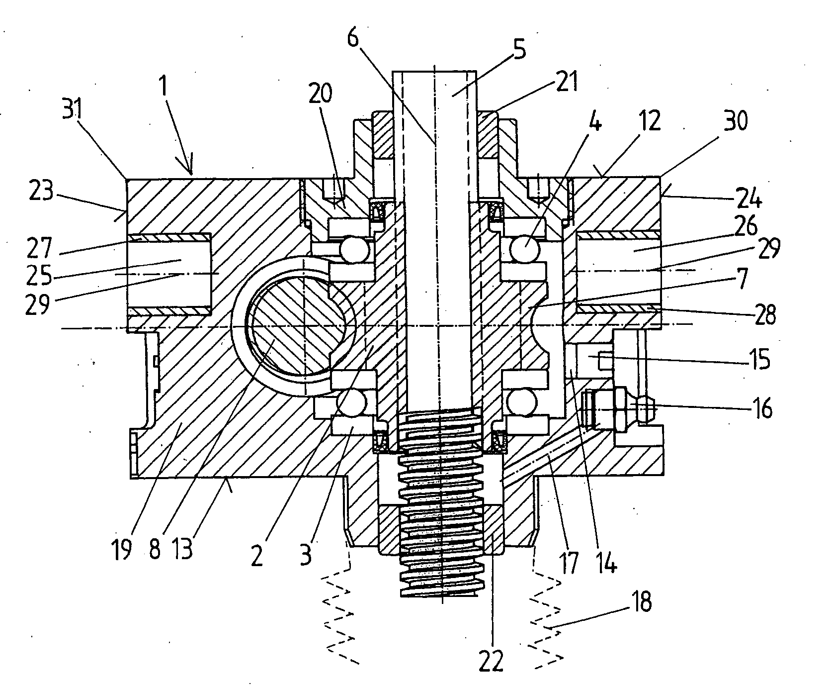
[0019] In the embodiment example of the invention shown in the drawings, a spindle nut 2 is supported in the gear housing 1 by axial bearings 3, 4 so as to be rotatable and not displaceable axially. The spindle nut 2 is arranged with its internal thread on the external thread of a spindle 5 which is displaceable axially, i.e., in direction of its longitudinal axis 6, by rotation of the spindle nut 2. The external thread of the spindle 5 can be constructed, e.g., in the form of a trapezoidal thread.

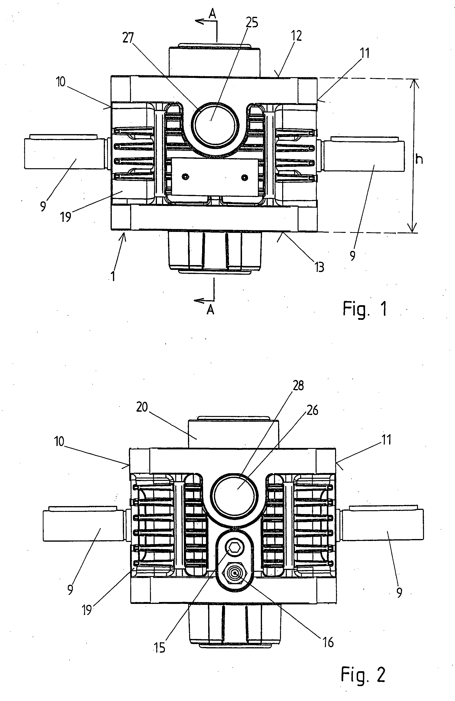
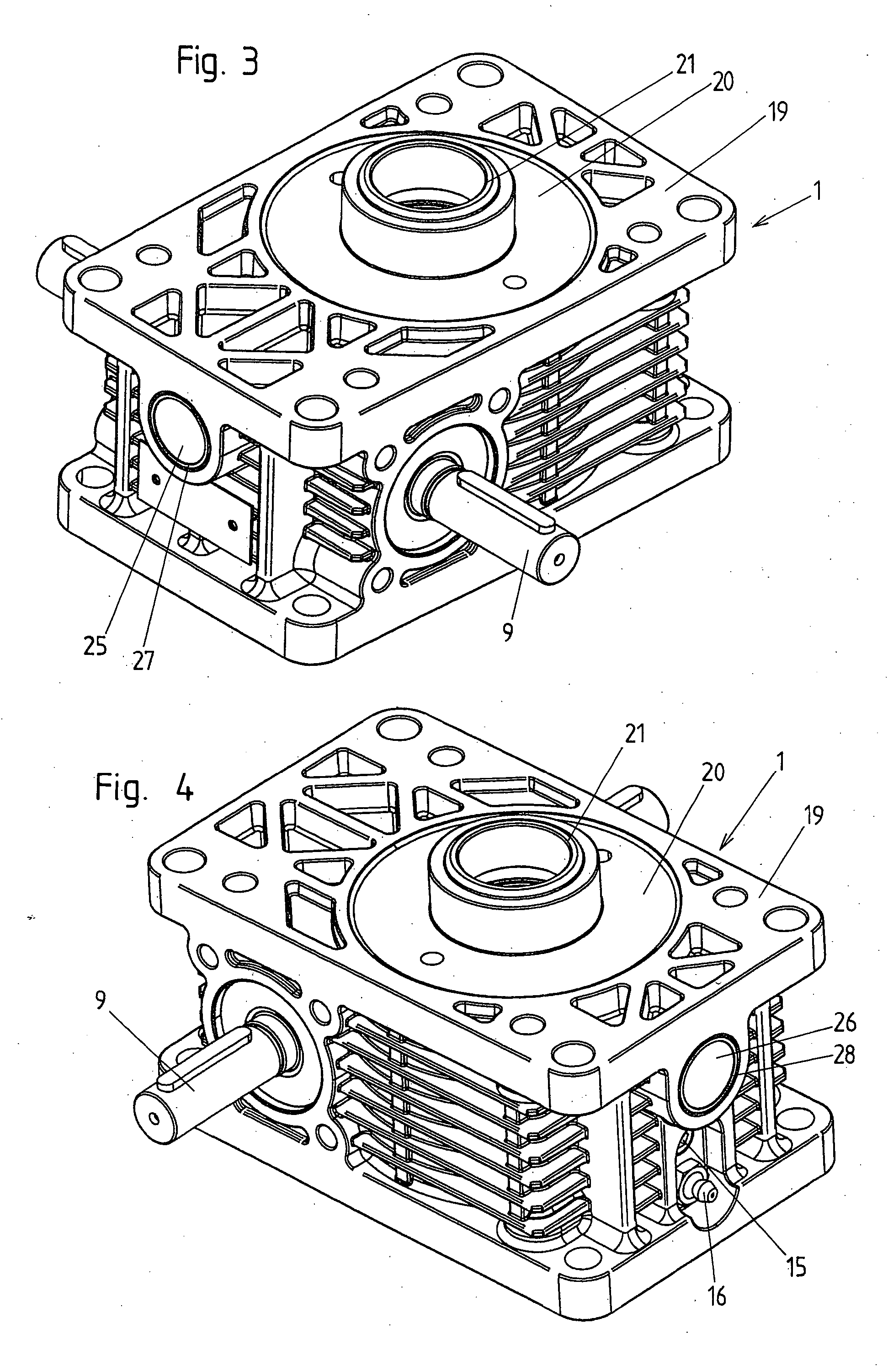
[0020] For rotation of the spindle nut 2, this spindle nut 2 has an external toothing 7 which engages with the toothing of a driving wheel 8. The external toothing 7 can be formed, for example, as a worm toothing and the driving wheel 8 can be constructed as a worm. The driving wheel 8 is driven by a driveshaft 9 which projects from opposite sides 10, 11 of the gear housing 1 in the embodiment example shown in the drawing. The rotatable bearing support of the driving wheel 8 can be carrie...


PUM


Abstract

An adjusting device for positioning a load comprises a spindle and a spindle nut which is arranged on the spindle. Either the spindle nut is supported in a gear housing so as to be rotatable and not axially displaceable and the spindle is axially adjustable by rotating the spindle nut for positioning the load, or the spindle is supported in the gear housing so as to be rotatable and not axially displaceable and the spindle nut is axially adjustable by rotating the spindle for positioning the load. The gear housing has blind holes on two oppositely located housing sides and the swivel bearing bushes are pressed into these blind holes for receiving swivel pins.

Description

CROSS-REFERENCE TO RELATED APPLICATIONS [0001] This application claims priority of Austrian Application No. GM 831 / 2004, filed Nov. 17, 2004, the complete disclosure of which is hereby incorporated by reference. BACKGROUND OF THE INVENTION [0002] a) Field of the Invention [0003] The invention is directed to an adjusting device for positioning a load, comprising a spindle, a spindle nut which is arranged on the spindle, and a gear housing in which either the spindle nut is supported so as to be rotatable and not axially displaceable, wherein the spindle is axially adjustable by rotating the spindle nut for positioning the load, or in which the spindle is supported so as to be rotatable and not axially displaceable, wherein the spindle nut is axially adjustable by rotating the spindle for positioning the load. [0004] b) Description of the Related Art [0005] Adjusting devices of the type mentioned above are known and are also called spindle lifting gear units, spindle nut gear units, o...

Claims


Application Information

Patent Timeline
Patent Type & Authority Applications(United States)
IPC IPC(8): F16H25/20
CPCB66F3/18F16H25/20Y10T74/18576F16H2025/209F16H2025/2037
Inventor ZIMMERMANN, JUERGEN
Owner ZIMMERMANN JUERGEN
Why Eureka
Try Eureka