Overvoltage protection element

a protection element and overvoltage protection technology, applied in the direction of overvoltage protection resistors, emergency protection arrangements for limiting excess voltage/current, overvoltage protection resistors, etc., can solve the problem of deterioration of the plug-in electrical connection between the overvoltage protection element and the bottom part of the device, and achieve the effect of more convenient production and more economic

Active Publication Date: 2012-12-18
PHOENIX CONTACT GMBH & CO KG
View PDF10 Cites 3 Cited by
  • Summary
  • Abstract
  • Description
  • Claims
  • Application Information

AI Technical Summary

Benefits of technology

[0009]A primary object of this invention is to provide an overvoltage protection element of the initially described type which can be produced more easily, and thus, more economically. Here, the overvoltage protection elements should have the same electrical and mechanical properties as the existing overvoltage protection elements.
[0010]This object is achieved in an overvoltage protection element of the initially described type in that the first terminal lug and the first connecting element are integrally connected to one another, the free end of the first connecting element which faces away from the overvoltage limiting component being made as a plug-in contact. Thus, in accordance with the invention, the first terminal lug of the overvoltage limiting component is made such that its free end itself is used as the connecting element. Because the first terminal lug and the first connecting element are made in one piece, the additional production step in which the terminal lug is connected to the connecting element by soldering or welding, which step is necessary in the prior art, is eliminated. In addition to simplification of the production process of the overvoltage production element, in the integral execution of the terminal lug and the connecting element in accordance with the invention it is also ensured that the “contact resistance” between the terminal lug and the connecting element is minimized.
[0012]According to another advantageous feature of the invention, the mechanical strength of the folded connecting element is increased by its individual layers being connected to one another positively, nonpositively, or bonded. Here, the connecting region is outside the contact region so that the contact properties of the connecting element do not change due to the implemented connection of the individual layers to one another.
[0013]In one especially preferred configuration of the overvoltage protection element in accordance with the invention, a positive connection is made between the first connecting element or the first terminal lug and the housing. During the process of plugging in and withdrawing the overvoltage protection element, a force acts on the overvoltage limiting component which is located in the housing, which force is proportional to the adhesive friction which must be overcome in order to insert the connecting element made as a plug-in contact into the corresponding socket of the bottom part of the device and to pull it out of the socket. By implementing a positive connection between the first connecting element and the housing, the plug-in and withdrawal forces are transmitted directly from the housing to the plug-in contact, or the forces acting on the plug-in contact are accommodated by the housing, so that the forces acting on the overvoltage limiting component are greatly reduced or even completely prevented in the plug-in or withdrawal process.

Problems solved by technology

In practice, the terminal lugs of the overvoltage limiting component generally have a relatively low material thickness so that the mechanical strength of the free end of the terminal lug acting as the connecting element cannot be enough to permanently withstand the forces which are active in plugging-in and withdrawing the overvoltage element without damage to the connecting element, and thus, deterioration of the plug-in electrical connection between the overvoltage protection element and the bottom part of the device.

Method used


Image

  • Overvoltage protection element
  • Overvoltage protection element
  • Overvoltage protection element

Examples


Embodiment Construction

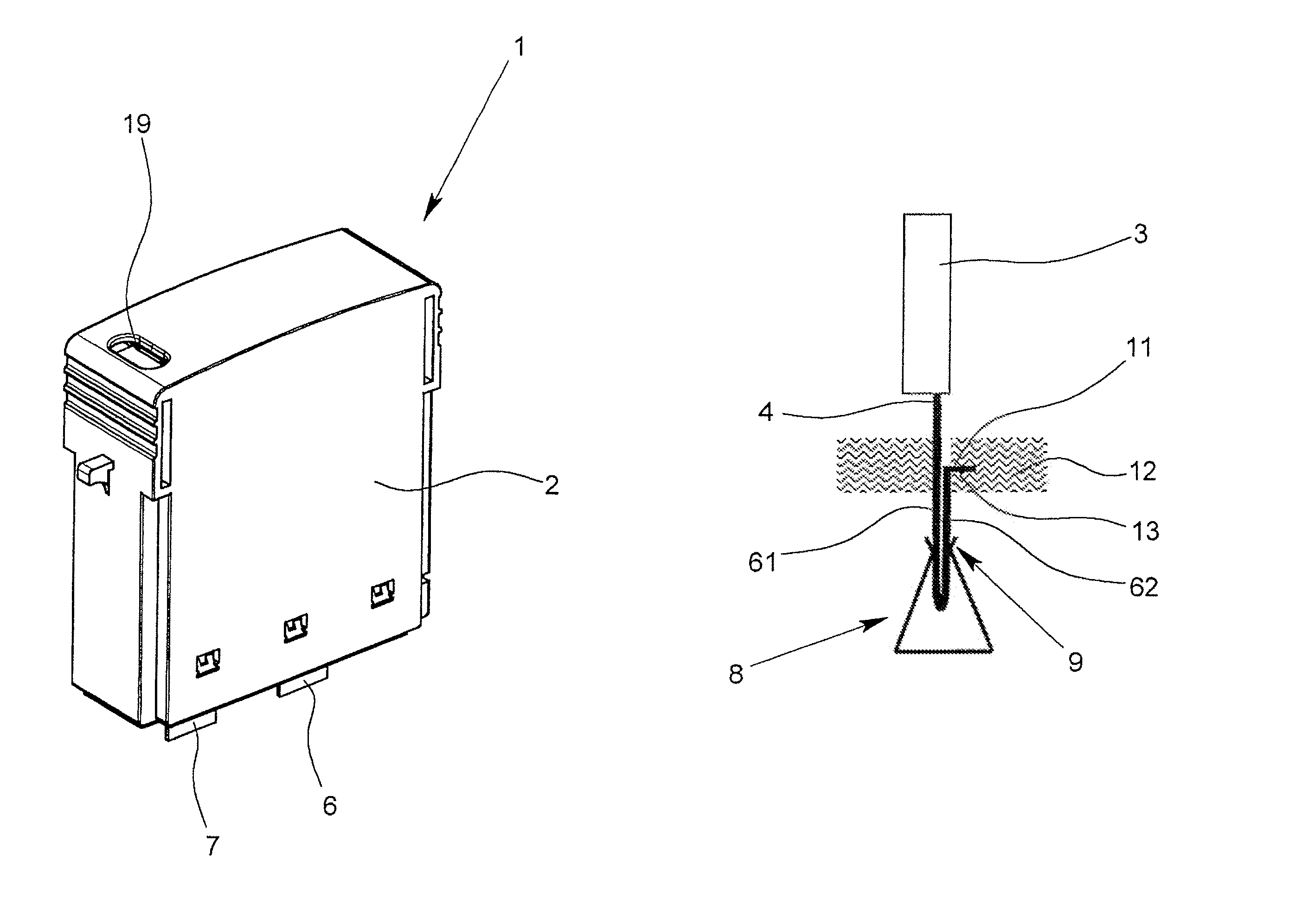
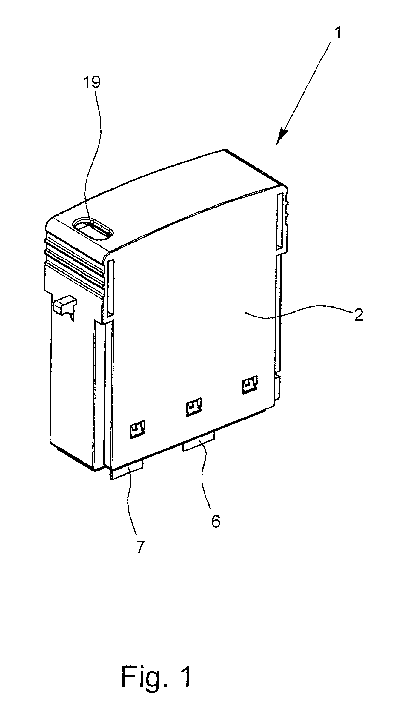
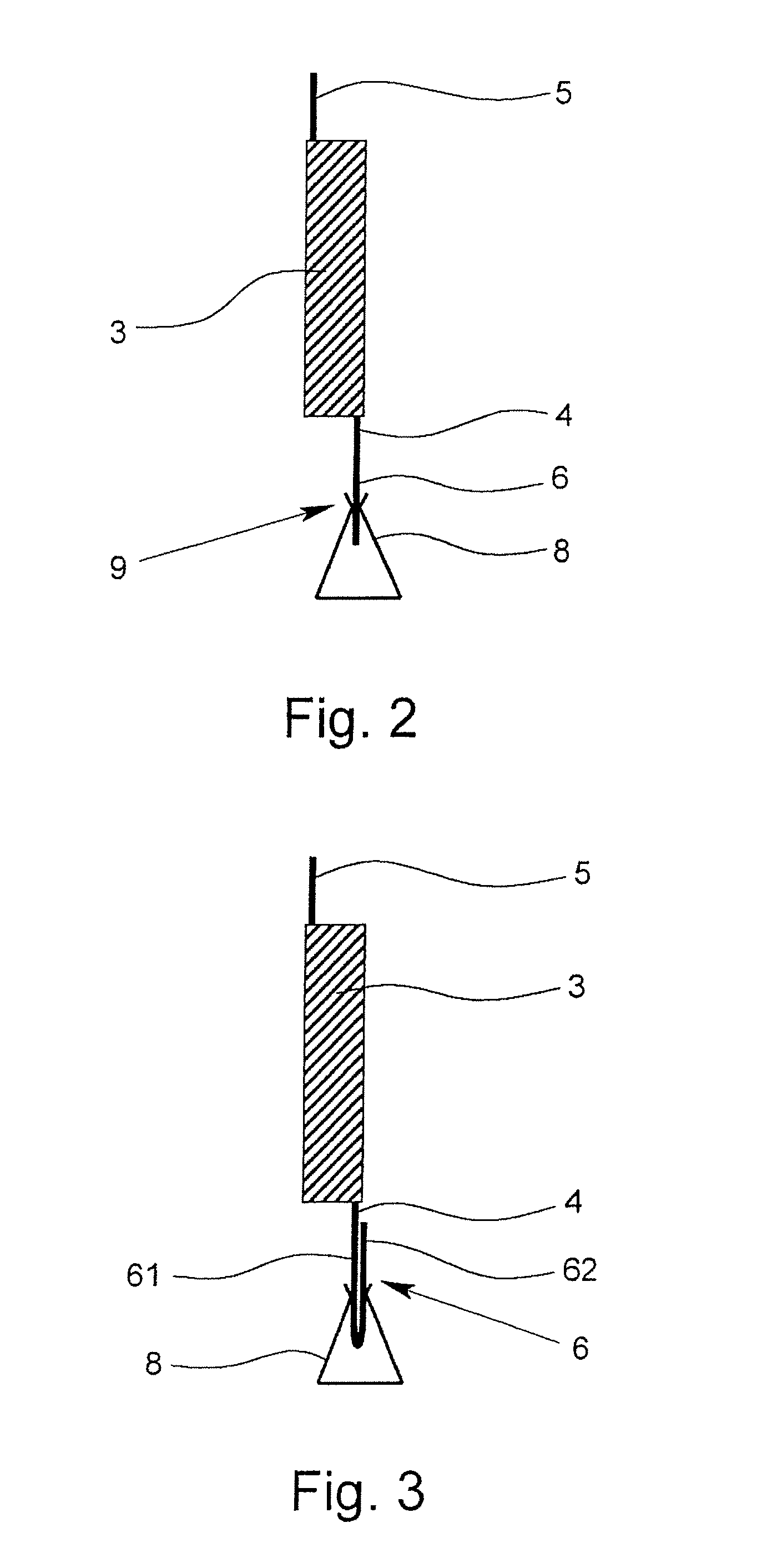
[0028]In FIG. 1, an overvoltage protection element 1 has a housing 2, there being an overvoltage limiting component in the housing 2. In the illustrated exemplary embodiments, the overvoltage limiting component is a varistor 3; alternatively, the overvoltage limiting component can also be formed by several varistors connected in parallel, especially a double varistor. Likewise, the overvoltage limiting component can also be a gas-filled surge arrester.

[0029]The two poles of the varistor 3 are each connected to a terminal lug 4, 5 in an electrically conductive manner, especially soldered or welded. The protective element 1 made as a protective plug moreover has two connecting elements 6, 7 which are made as plug-in contacts and which project out of the housing 2 through corresponding openings on the bottom of the overvoltage protection element 1. The plug-shaped connecting elements 6, 7 can be inserted into the corresponding sockets 8 of the bottom part of the device which is not sho...


PUM


Abstract

An overvoltage protection element with a housing, with at least one overvoltage limiting component which is located in the housing, especially a varistor, with two terminal lugs which are each connected to a respective pole of the overvoltage limiting component in an electrically conductive manner, especially soldered or welded, and with two connecting elements for electrical connection of the overvoltage protection element to the current path or signal path to be protected. In the normal state of the overvoltage protection element, the connecting elements are each in electrically conductive contact with a respective terminal lug. The overvoltage protection element can be produced especially easily and economically by the first terminal lug and the first connecting element being integrally connected to one another and by the free end of the first connecting element which faces away from the overvoltage limiting component being made as a plug-in contact.

Description

BACKGROUND OF THE INVENTION[0001]1. Field of the Invention[0002]The invention relates to an overvoltage protection element with a housing, with at least one overvoltage limiting component which is located in the housing, especially a varistor, with two terminal lugs which are each connected to one pole of the overvoltage limiting component in an electrically conductive manner, especially soldered or welded, and with two connecting elements for electrical connection of the overvoltage protection element to the current path or signal path to be protected, in the normal state of the overvoltage protection element the connecting elements each being in electrically conductive contact with one terminal lug at a time.[0003]2. Description of Related Art[0004]The known overvoltage protection elements are generally made as “protective plugs” which together form an overvoltage protection device with the bottom part of the device. For installation of such an overvoltage protection device which,...

Claims


Application Information

Patent Timeline
Patent Type & Authority Patents(United States)
IPC IPC(8): H02H1/00
CPCH01T4/02
Inventor TEGT, MICHAELDURTH, RAINERDEPPING, CHRISTIANWOSGIEN, JOACHIM
Owner PHOENIX CONTACT GMBH & CO KG
Why Eureka
Try Eureka