Reception device for a magnetic resonance tomography installation, having a phase shift-compensating amplifier

a technology of phase shift compensation and magnetic resonance tomography, which is applied in the direction of magnetic measurement, measurement devices, instruments, etc., can solve the problem of unergonomically bulky arrangements

Inactive Publication Date: 2005-08-30
SIEMENS HEALTHCARE GMBH
View PDF19 Cites 3 Cited by
  • Summary
  • Abstract
  • Description
  • Claims
  • Application Information

AI Technical Summary

Benefits of technology

[0007]An object of the present invention is to provide a reception device for a magnetic

Problems solved by technology

The known combiner also has the disadvantage that it requires a certain spatial volume for the circuitry, leading to unergonomically bulky arrangements, particularly in the man

Method used


Image

  • Reception device for a magnetic resonance tomography installation, having a phase shift-compensating amplifier
  • Reception device for a magnetic resonance tomography installation, having a phase shift-compensating amplifier
  • Reception device for a magnetic resonance tomography installation, having a phase shift-compensating amplifier

Examples


Embodiment Construction

[0024]For easier comprehension, a phase shift of exactly 90° between the received polarization components forms the basis of the discussion below. The considerations can be transferred to cases having a different phase shift.

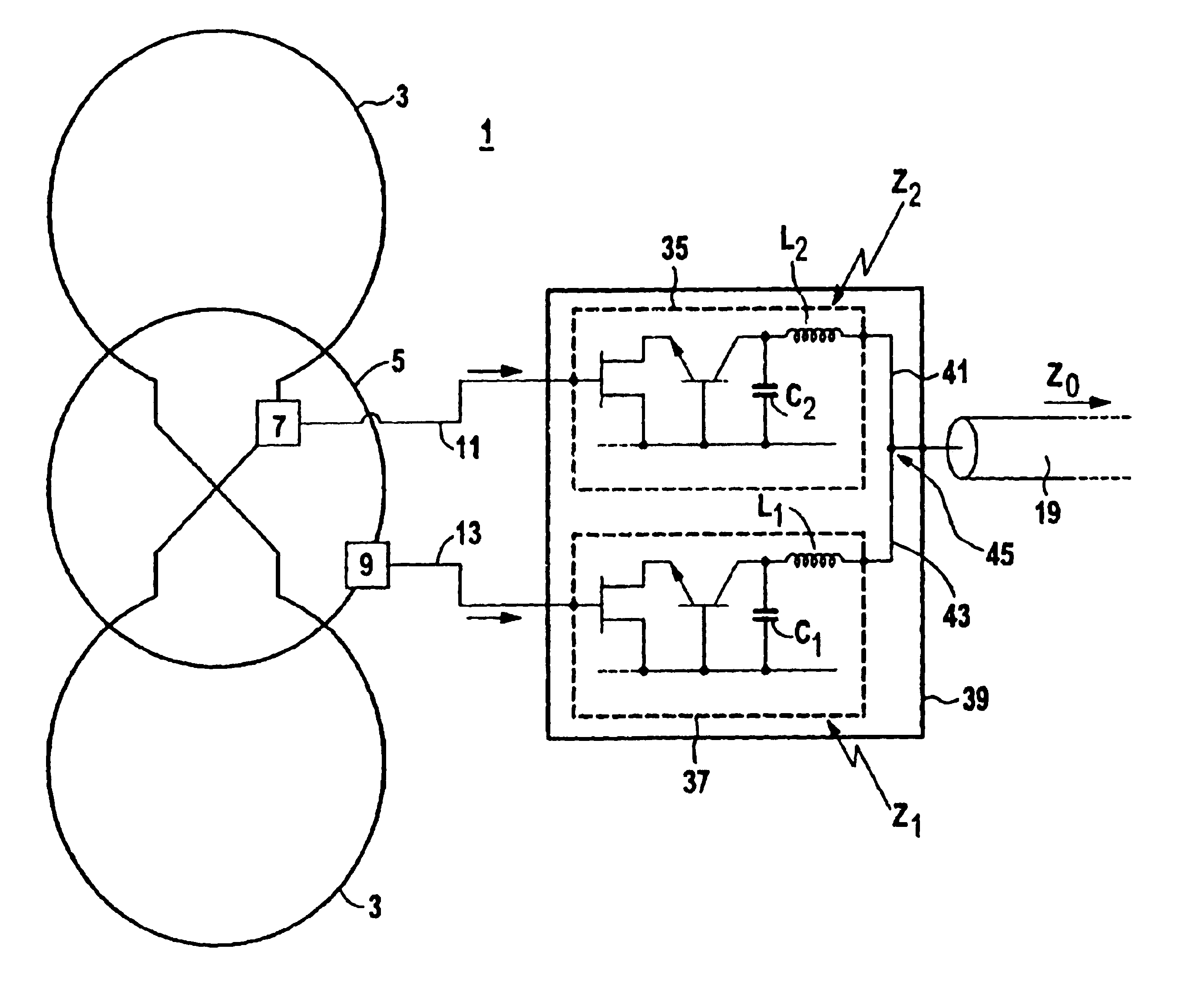
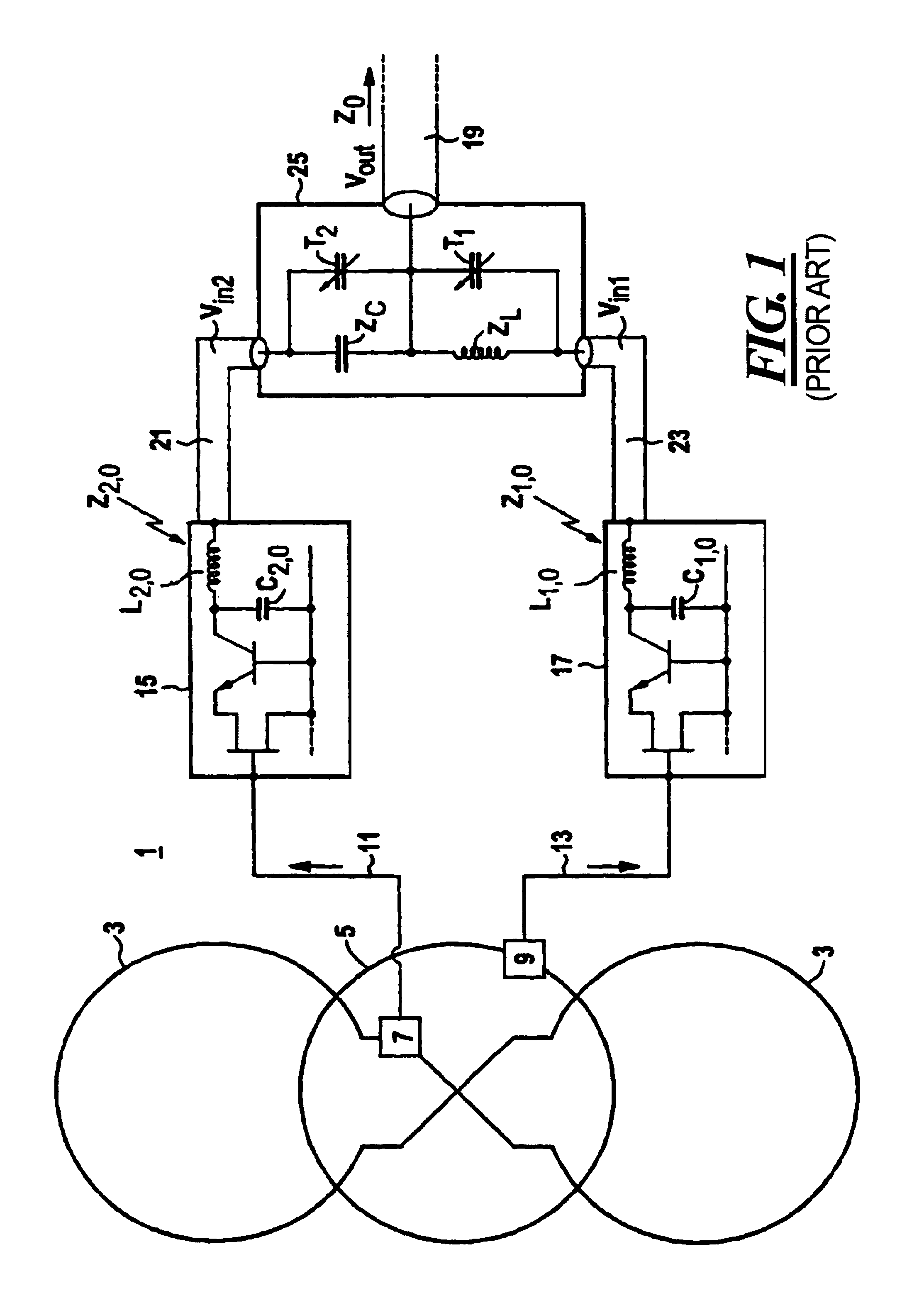
[0025]FIG. 1 shows a reception device 1 of a magnetic resonance tomography installation whose other component parts are not explicitly shown. The reception device 1 has a first reception coil 3 that is fashioned as a butterfly element. A second reception coil 5 fashioned as a loop element. Matching networks 7 and 9 are respectively integrated into the coil elements 3, 5, these serving the purpose of noise matching. The matching network 7 of the first reception coil 3 is connected via a line 11 to a first pre-amplifier or to a first amplifier 15. In the same way, the matching network 9 of the second reception coil 5 is in communication via a line 13 with a second pre-amplifier or a second amplifier 17.

[0026]The output signals of the two amplifiers 15, 17—respecti...


PUM


Abstract

A reception device for detecting an electromagnetic radio-frequency wave emitted by the examination subject in a magnetic resonance tomography installation has two reception coils and amplifiers arranged following these coils. The mutually phase-delayed reception signals of the reception coils are tapped by a common signal line. For compensating the phase shift one of the amplifiers is or both amplifiers are directed between the two reception signals. A separate combiner can thereby be advantageously eliminated.

Description

BACKGROUND OF THE INVENTION[0001]1. Field of the Invention[0002]The present invention is directed to a reception device for detecting an electromagnetic radio-frequency wave emitted by the examination subject of a nuclear magnetic resonance tomography installation, of the type having a first reception coil, a first amplifier allocated to the first reception coil, a second reception coil whose reception signal is phase-shifted with respect to the reception signal of the first reception coil, particularly by a phase angle of 90°, comprising a second amplifier allocated to the second reception coil, and a common signal line via which the output signals of the two amplifiers are carried off.[0003]2. Description of the Prior Art[0004]For receiving the circularly polarized radio-frequency signal, two orthogonal polarization components are separately received in a magnetic resonance tomography installation. In, for example, a vertical field apparatus, a first polarization component is rece...

Claims


Application Information

Patent Timeline
IPC IPC(8): G01R33/32G01R33/36
CPCG01R33/3621
Inventor WANG, JIANMIN
Owner SIEMENS HEALTHCARE GMBH
Why Eureka
Try Eureka